Small signal gain is the gain in the amplifier's linear region of operation. This is typically measured at a constant input power over a swept frequency. Gain flatness is the measure of the variation of gain over a specified frequency range.
See other Amplifier Parameter topics
RF amplifier gain is defined as the difference in power between the amplifier output signal and the input signal. It is assumed that both input and output impedances of the amplifier are the same as the characteristic impedance of the system.
Gain is called S21 using S-parameter terminology
Gain is expressed in dB-a logarithmic ratio of the output power relative to the input power.
Gain can be calculated by subtracting the input from the output levels when both are expressed in dBm, which is power relative to 1 milliwatt.
Amplifier gain is most commonly specified as a minimum value over a specified frequency range. Some amplifiers specify both minimum and maximum gain, to ensure that subsequent stages in a system are not under or over driven.
Flatness specifies how much the amplifier's gain can vary over the specified frequency range. Variations in the flatness of the amplifier's gain can cause distortion of signals passing through the amplifier.
Deviations in gain over the bandwidth of interest will induce distortion in the transmitted signal because frequency components are not amplified equally. Small-signal gain allows you to quantify the amplifier's gain at a particular frequency in a 50-ohm system. Flatness allows you to view the deviations in the amplifier's gain over a specified frequency range in a 50-ohm system.
The amplifier may respond very differently at various temperatures. The tests should be done when the amplifier is at the desired operating temperature.
The output power of the amplifier should be sufficiently attenuated if necessary. Too much output power could:
damage the analyzer receiver
exceed the input compression level of the analyzer receiver, resulting in inaccurate measurements.
Attenuation of the amplifier's output power can be accomplished using:
attenuators
couplers
The frequency-response effects and mismatches of the attenuators and couplers must be accounted for during calibration since they are part of the test system. Proper error-correction techniques can reduce these effects.
The frequency response is the dominant error in a small-signal gain and flatness measurement setup. Performing a thru-response measurement calibration significantly reduces this error. For greater accuracy, perform a 2-port measurement calibration.
Reducing IF bandwidth or using averaging improves measurement dynamic range and accuracy, at the expense of measurement speed.
Preset the analyzer.
Select an S21 measurement parameter.
Set the analyzer's source power to be in the linear region of the amplifier's output response (typically 10-dB below the 1-dB compression point).
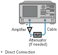
Select an external attenuator (if needed) so the amplifier's output power will be sufficiently attenuated to avoid causing receiver compression or damage to the analyzer's port-2.

Connect the amplifier as shown in the following graphic, and provide the dc bias.
Select the analyzer settings for your amplifier under test.
Remove the amplifier and perform a measurement calibration. Be sure to include the attenuator and cables in the calibration setup if they will be used when measuring the amplifier.
Save the instrument-state to memory.
Reconnect the amplifier.
Scale the displayed measurement for optimum viewing and use a marker to measure the small signal gain at a desired frequency.
Measure the gain flatness over a frequency range by using markers to view the peak-to-peak ripple.
Print or save the data to a disk.
This type of measurement can be automated.
![]()