The output I/O markers can pass markers generated earlier in the system or can replace them with dynamically-generated markers. In configurations where channel summing occurs, only the markers from one of the channels may be used. You must specify which channel's markers are used.
|
|
For a DSIM (N5102A Digital Signal Interface Module) at the output of the PXB, Marker 1 from the PXB will map into Marker 1 of the DSIM, however, Marker 3 from the PXB will map into Marker 2 of the DSIM. |
Choices: For Baseband Generator Block (BB
Gen1, BB Gen2 , BB Gen3 , BB Gen4)
-or- for Input
I/O Block (I/O1, I/O2)
Default: BB Gen1 / A1
Specifies which channel markers can be used by the output I/O. In single channel configurations, the single channel is the Master Channel, by default. In configurations where channel summing occurs, you may select the Master Channel.
|
|
It is not possible to select individual markers from different channels. |
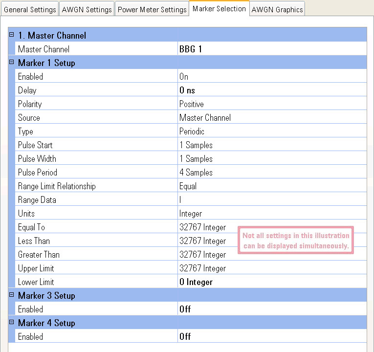
The PXB provides for three markers which are available at each point on the baseband generator waveform signal. These markers are sent on separate lines. The setup for the three markers are labeled Marker 1 Setup, Marker 3 Setup, and Marker 4 Setup. Marker 2 is reserved for internal use by the PXB.
Choices:
Off, On
Default Value: On
Turns on the individual marker. When Enabled is set to On, additional marker settings that are used for the marker setup are also displayed. When Enabled is set to Off, zero is the output.
Range: 0 s to Time Required to Play 1,024
Samples (Varies based on Sample Rate)
Default Value: 0 s
Resolution: Varies based on external instrument sample rate
Dependency: Displayed only when Enabled is set to On
Sets the amount of time that the marker is delayed. Once the waveform file has started playing, the marker will play after the delay period has been achieved.
The resolution for the delay is dependant on the sample rate of the external instrument at the output. When the PXB is connected to:
N5182A MXG with a sample rate of 125 MHz, the resolution is 8 ns (1/125 MHz) up to a maximum of 8.192 us.
E4438C ESG with a sample rate of 100 MHz, the resolution is 10 ns (1/100MHz) up to a maximum of 10.240 us.
N5102A Digital Signal Interface Module appears to have a resolution of 1 ns, however the delay value can be adjusted based on the actual resolution is defined by the N5102A module Output Sample Rate entered (1/Output Sample Rate). The N5102A output sample rate is identified by the PXB's I/O only after the Play button is selected to start playing the waveform. When this occurs, the entered delay is compared to the calculated resolution value of the delay and then is rounded to the nearest whole resolution value.
For example, if you entered an output sample rate of 125 MHz for the N5102A and entered 15 ns for Delay value, the PXB calculates the resolution as 8 ns (1/125 MHz) and rounds the 15 ns Delay entry to 16 ns (because it is the nearest multiple of the calculated 8 ns resolution). There is no warning of a change when this occurs.
The maximum allowed Delay value is 1/ 1000 * 1024, which is 1.024 seconds, but the value will be clipped to the maximum value based on the output sample rate. This maximum is based on the lowest possible N5102A clock.
Choices:
Positive, Negative
Default Value: Positive
Dependency: Displayed only when Enabled is set to On
Sets the marker output state when the marker source is turned on and off.
Positive
This choice sets the marker output signal to be High (1), when the marker
points from the marker source are On. When the marker points from the
source are Off, the marker output signal is set to Low (0).
Negative
This choice sets the marker output signal to be Low (0), when the marker
points from the marker source are On. When the
marker points from the source are Off, the marker output signal is set
to High (1).
Choices:
Master Channel, Dynamic
Default Value: Master Channel
Dependency: Displayed only when Enabled is set to On
Sets the source that is used to generate the markers. The options include:
Master Channel
This choice uses the source specified in the Master Channel setting to
specify the marker state. The Master Channel selection is either a baseband
generator block or in the case of "(ext in)" configurations,
an input I/O block.
Dynamic
This choice generates markers based on a value of each waveform sample.
This allows you to generate markers based on the values of both summed
and degraded waveforms. The markers are based on the marker definitions
that you create when Dynamic is selected. This dynamic marker definition
is used to control the marker generation while the waveform file is played.
Choices:
Periodic, Range Detect, Zero Detect
Default Value: Periodic
Dependency: Displayed only when Source is set to Dynamic
Allows you to dynamically control the events that will turn the marker on and off.
Periodic
This choice sets the marker signal to be on and off at intervals defined
by the Pulse Start
(the number of samples to wait until the first marker pulse is started),
Pulse Width (the
number of samples that the marker pulse is turned on), and Pulse Period (the number of samples for one complete
cycle of the marker pulse, which is number of samples of the pulse period
plus the number of samples of off time between two pulses) settings.  Examples…
Range Detect
This choice identifies the marker signal to be on and off when the waveform
signal meets specific criteria that you define. The criteria are defined
by a variety of the settings listed below Type
when Range Detect is selected.
The Range Detect choice has an additional selection, Range Limit Relationship, which determines
which of four additional range setting styles are used. The Range Limit
Relationship choices are Equal,
Less, Greater,
and Range.
Zero Detect
This choice identifies the marker signal to be on while the waveform signal
value equals zero and off at other times. While the waveform signal is
at the zero value, the marker is turned on until the signal is no longer
at zero. Example…
Range: 1 to 1099511627775
(240-1) Samples
Default Value: 1 Sample
Resolution: 1 Sample
Dependency: Displayed only when Type is set to Periodic
Sets the waveform sample number to turn on the first marker pulse. When this waveform sample point is played, the first marker pulse is turned on.
Range: 1 to 4294967295 (232-1) Samples
Default Value: 1 Sample
Resolution: 1 Sample
Dependency: Displayed only when Type is set to Periodic
Sets the number of waveform samples as the width of the marker pulse. The pulse width is the number of samples that the marker pulse is turned on. If a valid integer is not entered, the entry is rounded up to the next valid integer.
Range: 4 to 1099511627775
(240-1) Samples
Default Value: 4 Samples
Resolution: 1 Sample
Dependency: Displayed only when Type is set to Periodic
Sets the number of waveform samples used as the period for one marker cycle. This is the number of waveform samples of one complete pulse cycle, both the on and off periods. The pulse period may be set as an integer, greater than or equal to 4, representing the number of samples. If a valid integer is not entered, the entry is rounded up to the next valid integer.
Choices:
Equal, Less, Greater, Range
Default Value: Equal
Dependency: Displayed only when Type is set to Range Detect
Sets the relationship for the range limits that the range detection process uses to compare the waveform sample against when determining the marker state.
Equal
This choice sets the range detection process to turn the marker on when
the waveform sample value is equal to the value that you specify with
the Range Data and the Equal
To parameters. Example…
Less
This choice sets the range detection process to turn the marker on when
the waveform sample value is less than the value that you specify with
the Range Data and the Less
Than parameters. Example…
Greater
This choice sets the range detection process to turn the marker on when
the waveform sample value is greater than the value that you specify with
the Range Data and the Greater
Than parameters. Example…
Range
This choice sets the range detection process to turn the marker on when
the waveform sample value is within the values that you specify with the
Range Data, Upper
Limit, and Lower Limit
parameters. Example…
Choices:
I, Q, Power
Default Value: I
Dependency: Displayed only when Marker Type is set to Range Detect
Sets the type of data that the range detection process uses to compare
the waveform sample against when determining the marker state. The maximum
and minimum values change depending on this selection. Example…
I
This choice sets the range detection process to use the voltage of the
I portion of the waveform sample value when determining the marker state.
Q
This choice sets the range detection process to use the voltage of the
Q portion of the waveform sample value when determining the marker state.
Power
This choice sets the range detection process to use the power of the waveform
sample value when determining the marker state.
Choices:
Integer, dB, %
Default Value: Integer
Dependency: Displayed only when Type is set to Range Detect
Sets the units of the waveform sample for which the range detection process checks when determining the marker state. The Unit values change depending on the Range Data selection.
Integer
This choice sets the range detection process to compare the DAC integer
value of the waveform sample when determining the state of the marker.
dB
This choice sets the range detection process to compare the measured power
of the waveform sample when determining the state of the marker.
%
This choice sets the range detection process to compare the percentage
between the minimum and maximum values of the waveform sample when determining
the state of the marker.
Range:
when Units is set to Integer and Range Data is set to I or Q: –32768 to 32767
when Units is set to Integer and Range Data is set to Power: 0
to 46340
when Units is set to dB and Range Data is set to I or Q: –Infinity (–96.3)
to 0 dB
when Units is set to dB and Range Data is set to Power: –Infinity (–43.6)
to 3 dB
when Units is set to % and Range Data is set to I or Q: 0
to 100 %
when Units is set to % and Range Data is set to Power: 0
to 100 %
Default Value:
when Range Data is set to I or Q: 32767 Integer,
0.0 dB, 100 %
when Range Data is set to Power: 32767 Integer, 1.5 dB, 70.7 %
Resolution: 1 Integer, 0.1 dB, 0.1 %
Dependency: Displayed only when Range Limit Relationship is set to Equal
Sets the limit value of the dynamic marker when the Range Limit Relationship is set to Equal. The marker is turned on while the waveform value is at the Equal To value.
Range:
when Units is set to Integer and Range Data is set to I or Q: –32768 to 32767
when Units is set to Integer and Range Data is set to Power: 0
to 46340
when Units is set to dB and Range Data is set to I or Q: –Infinity (–96.3)
to 0 dB
when Units is set to dB and Range Data is set to Power: –Infinity (–43.6)
to 3 dB
when Units is set to % and Range Data is set to I or Q: 0
to 100 %
when Units is set to % and Range Data is set to Power: 0
to 100 %
Default Value:
when Range Data is set to I or Q: 32767 Integer,
0.0 dB, 100 %
when Range Data is set to Power: 32767 Integer, 1.5 dB, 70.7 %
Resolution: 1 Integer, 0.1 dB, 0.1 %
Dependency: Displayed only when Range Limit Relationship is set to Less
Sets the limit value of the dynamic marker when the Range Limit Relationship is set to Less. The marker is turned on whenever the waveform value decreases below the Less Than value.
Range:
when Units is set to Integer and Range Data is set to I or Q: –32768 to 32767
when Units is set to Integer and Range Data is set to Power: 0
to 46340
when Units is set to dB and Range Data is set to I or Q: –Infinity (–96.3)
to 0 dB
when Units is set to dB and Range Data is set to Power: –Infinity (–43.6)
to 3 dB
when Units is set to % and Range Data is set to I or Q: 0
to 100 %
when Units is set to % and Range Data is set to Power: 0
to 100 %
Default Value:
when Range Data is set to I or Q: 32767 Integer,
0.0 dB, 100 %
when Range Data is set to Power: 32767 Integer, 1.5 dB, 70.7 %
Resolution: 1 Integer, 0.1 dB, 0.1 %
Dependency: Displayed only when Range Limit Relationship is set to Greater
Sets the limit value of the dynamic marker when the Range Limit Relationship is set to Greater. The marker is turned on whenever the waveform value increases above the Greater Than value.
Range:
when Units is set to Integer and Range Data is set to I or Q: –32768 to 32767
when Units is set to Integer and Range Data is set to Power: 0
to 46340
when Units is set to dB and Range Data is set to I or Q: –Infinity (–96.3)
to 0 dB
when Units is set to dB and Range Data is set to Power: –Infinity (–43.6)
to 3 dB
when Units is set to % and Range Data is set to I or Q: 0
to 100 %
when Units is set to % and Range Data is set to Power: 0
to 100 %
Default Value:
when Range Data is set to I or Q: 32767
Integer, 0.0 dB, 100 %
when Range Data is set to Power: 32767
Integer, 1.5 dB, 70.7 %
Resolution: 1 Integer, 0.1 dB, 0.1 %
Dependency: Displayed only when Range Limit Relationship is set to Range
Sets the value of the upper range limit of the dynamic marker when the Range Limit Relationship is set to Range. The marker is on whenever the waveform value is less than the Upper Limit value and greater than the Lower Limit value.
Range:
when Units is set to Integer and Range Data is set to I or Q: –32768 to 32767
when Units is set to Integer and Range Data is set to Power: 0
to 46340
when Units is set to dB and Range Data is set to I or Q: –Infinity (–96.3)
to 0 dB
when Units is set to dB and Range Data is set to Power: –Infinity (–43.6)
to 3 dB
when Units is set to % and Range Data is set to I or Q: 0
to 100 %
when Units is set to % and Range Data is set to Power: 0
to 100 %
Default Value:
when Range Data is set to I or Q: –32768 Integer, –Infinity
(–96.3) dB, 0 %
when Range Data is set to Power: 0 Integer,
–Infinity (–43.6)
dB, 0 %
Resolution: 1 Integer, 0.1 dB, 0.1 %
Dependency: Displayed only when Range Limit Relationship is set to Range
Sets the value of the lower range limit of the dynamic marker when the Range Limit Relationship is set to Range. The marker is on whenever the waveform value is less than the Upper Limit value and greater than the Lower Limit value.
Refer to Marker 1 Setup for individual parameter descriptions.
Refer to Marker 1 Setup for individual parameter descriptions.
This channel is disabled when the output I/O block is connected to a Digital Signal Interface Module (DSIM).
General
Settings
AWGN Settings
AWGN Graphics