|
|
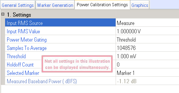
Power Calibration Considerations
|
Choices: Measure, Use Last RMS, User Entered,
Waveform Header, Application Provided
Default Value: Depends on selected waveform type
Identifies where the PXB gets the RMS voltage value of the waveform to ensure the correct amplitude of the waveform at the output of the signal generator. This RMS voltage value is used to calibrate the power of the system (the PXB and the signal generator) when the power calibration is performed.
When a binary waveform (.bin) is selected as the Waveform Source Name, the PXB automatically selects Measure as the RMS Source selection. This remains the selection until you change it manually or until you change the waveform type to (.wfm).
When a Signal Studio waveform (.wfm) is selected as the Waveform Source Name on the baseband generator's General Settings tab, the PXB automatically selects Waveform Header as the RMS Source selection. You may change this setting to any of the other selections. This remains the selection until you change it manually or until you change the waveform type to (.bin).
Whenever changes happen automatically, the PXB displays an informational message on the Error Bar: ”Power calibration settings have been changed to match the current waveform type”.
Measure
This choice pre-plays the selected waveform and measures the waveform's
RMS voltage with a power meter that is located at the output of the baseband
generator block. The measured RMS voltage is for the power calibration.
When Measure is selected, the Power Meter Gating setting selects whether
a voltage threshold or a marker is used to identify the portions of the
waveform that will be measured.
Use Last RMS
This choice uses the last RMS voltage (either measured, user entered, or
read from the waveform header) for the power calibration. This is very
useful when you are "re-playing" a waveform that was measured
because it eliminates the time needed to actually measure the waveform
RMS.
|
|
If the waveform is changed, the last RMS voltage value is no longer valid and the waveform needs to be measured again. |
User Entered
This choice allows you to enter the RMS voltage of a waveform directly.
If you have created a waveform and know its RMS voltage, entering its
voltage is quicker than measuring the waveform.
Waveform Header
This choice reads the RMS voltage from the waveform header. For example,
Signal Studio waveforms have the RMS voltage information in the header,
so this choice would read the RMS voltage from the header and save the
time of measuring the waveform.
Application Provided
This choice selects an application calculated value to input the RMS value when using real-time Signal Studio technologies.
Range: 0 to 1.414214 V
Default Value: 1.000000 V
Resolution: 1 µV
Dependency: Displayed only when RMS Source is set to User Entered or Waveform
Header
Active
only when RMS Source is set to User Entered
Sets the known RMS voltage of a waveform when RMS Source is set to User Entered and displays the voltage that is read from a waveform header when RMS Source is set to Waveform Header.
|
|
An incorrect RMS voltage results in incorrect output power at the signal generator and an incorrect SNR if the AWGN block is enabled. |
Choices: Threshold, Marker
Default Value: Threshold
Dependency: Displayed only when RMS Source is set to Measure
Selects the method used to identify which waveform samples that are measured when determining the waveform's RMS voltage. An illustration showing both Power Meter Gating choices can be viewed at Power Calibration Graphics.
Threshold
This choice allows you to set a threshold level to tell the PXB when to
measure the waveform. When the waveform voltage level meets or exceeds
the threshold level, the voltage for the waveform sample is used to determine
the waveforms RMS voltage. When the waveform voltage level is less than
the threshold level, the voltage for the waveform sample is not used to
determine the waveforms RMS voltage.
Marker
This choice uses a marker, identified by the Marker selection, to tell the PXB when to measure the
waveform. When the marker is turned on, the voltage for the waveform sample
is used to determine the waveform's RMS voltage. When the marker is turned
off, the voltage for the waveform sample is not used to determine the
waveform's RMS voltage. The marker criteria is set using the Marker Generation tab.
Range: 4 to 549755813887
Default Value: 1048576
Resolution: Rounds off to the nearest power of 2 (2n)
Dependency: Displayed only when RMS Source is set to Measure
Specifies the number of samples that are averaged when calculating the RMS voltage. When the waveform is measured during the pre-play, the PXB measures the specified number of samples that meet the criteria set by the threshold or marker settings and then uses these sample RMS voltage values to calculate the mean RMS voltage for the subsequent power calibration. Be sure to set this entry to a number that is equal to or larger than the part of the waveform that you want to measure.
Range: 0 to 1.414214 V
Default Value: 0.001 V
Resolution: 10 µV
Dependency: Displayed only when Power Meter Gating is set to Threshold
Defines the threshold voltage used to determine when the waveform sample voltage measurement is used to determine the waveform's RMS voltage. An illustration showing an example of using a threshold can be viewed at Power Calibration Graphics.
Range: 0 to 65,535 (216–1)
Default Value: 0
Resolution: 1
Dependency: Displayed only when Power Meter Gating is set to Threshold
Allows you to specify the number of consecutive waveform samples that must meet or exceed the threshold voltage level before the waveform sample is used to determine the waveforms RMS voltage. If the number of consecutive waveform samples is not met, the sample voltages are not used. This setting is useful if the waveform has an inconsistent structure or to eliminate glitches. An illustration showing an example of using Holdoff Sample Count can be viewed at Power Calibration Graphics.
Choices: Marker 1, Marker 3, Marker 4
Default Value: Marker 1
Dependency: Displayed only when Power Meter Gating is set to Marker
Selects which marker is used to define when the waveform is measured to determine the RMS voltage. An illustration showing an example of using a marker for power calibration can be viewed at Power Calibration Graphics.
Displays the measured BBG power (before BBG Runtime Scaling). The value is displayed in dBFS (dB, relative to full-scale voltage of 1.4142V).
General Settings
Marker Generation
Power Calibration Graphics