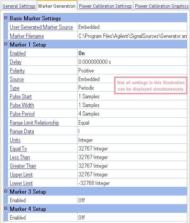
Markers cannot be changed while the waveform is playing.
Choices: Embedded, User File
Default Value: Embedded
Identifies whether the source for the markers will be embedded data from the waveform file or if the source is from a separate user-created marker file. Three marker positions (markers 1, 3, and 4) are read from the file. Marker 2 data is ignored. The marker file contains the same number of bytes as there are waveform points.
Embedded
This choice selects embedded marker data as the source for the waveform
markers, i.e., waveforms generated using a Signal Studio application.
User File
This choice selects a separate user-created file as the marker source for
the waveform. For an example of a user-created marker file, refer to Marker Files.
Dependency: Displayed only when User Generated Marker Source is set to User File
Selects the file to be used for the marker data. Marker Filename allows you to identify a separate file, other than the waveform file, as the source of the marker data.
The PXB provides for three markers which are available at each point on the baseband generator waveform signal. The setup for the three markers are labeled Marker 1 Setup, Marker 3 Setup, and Marker 4 Setup. Marker 2 is reserved for internal use by the PXB.
Agilent Signal Studio software applications typically use markers 1, 3 and 4. They do not use marker 2. Therefore, Signal Studio markers which map one for one into the PXB:
Signal Studio marker 1 to the PXB marker 1
Signal Studio marker 3 to the PXB marker 3
Signal Studio marker 4 to the PXB marker 4
|
|
For a DSIM (N5102A Digital Signal Interface Module) at the output of the PXB, Marker 1 from the PXB will map into Marker 1 of the DSIM, however, Marker 3 from the PXB will map into Marker 2 of the DSIM. |
Choices: Off, On
Default Value: On
Turns on the individual marker. When Enabled is set to On, additional marker settings that are used for the marker setup are also displayed. When Enabled is set to Off, zero is the output.
Range: 0 s to Time Required to Play 1,024
Samples (Varies based on Sample Rate)
Default Value: 0 s
Resolution: 1/Sample Rate
Dependency: Displayed only when Enabled is set to On
Sets the amount of time that the marker is delayed. Once the waveform file has started playing, the marker will play after the delay period has been achieved. The maximum delay is the time required to play 1,024 samples, which may be calculated by the equation:
![]()
Choices: Positive, Negative
Default Value: Positive
Dependency: Displayed only when Enabled is set to On
Sets the marker output state when the marker source is turned on and off.
Positive
This choice sets the marker output signal to be High (1), when the marker
points from the marker source are On. When the marker points from the
source are Off, the marker output signal is set to Low (0).
Negative
This choice sets the marker output signal to be Low (0), when the marker
points from the marker source are On. When the
marker points from the source are Off, the marker output signal is set
to High (1).
Choices: Embedded, User File, Dynamic
Default Value: Embedded or User File depending on
User Generated Marker Source selection
Dependency: Displayed only when Enabled is set to On
Sets the source that is used to generate the markers. The options include:
Embedded
When Embedded is selected as the
User Generated Marker Source setting,
this choice uses the marker information that is embedded in the baseband
generators waveform source file specify the marker states. This selection
provides the marker control afforded by the Signal Studio software creating
the waveform file.
User File
When User File is selected as the
User Generated Marker Source setting,
this choice uses the marker source file specified in the Marker
Filename to specify the marker states. This selection provides
complete marker control for each waveform sample point.
Dynamic
This choice generates markers on the fly based on the waveform data or
on periodic functions.
Choices: Periodic, Range Detect, Zero Detect
Default Value: Periodic
Dependency: Displayed only when Source is set to Dynamic
Allows you to dynamically control the events that will turn the marker on and off.
Periodic
This choice sets the marker signal to be on and off at intervals defined
by the Pulse Start
(the number of samples to wait until the first marker pulse is started),
Pulse Width (the
number of samples that the marker pulse is turned on), and Pulse Period (the number of samples for one complete
cycle of the marker pulse, which is number of samples of the pulse period
plus the number of samples of off time between two pulses) settings.  Examples…
Range Detect
This choice identifies the marker signal to be on and off when the waveform
signal meets specific criteria that you define. The criteria are defined
by a variety of the settings listed below Type
when Range Detect is selected.
The Range Detect choice has an additional selection, Range Limit Relationship, which determines
which of four additional range setting styles are used. The Range Limit
Relationship choices are Equal,
Less, Greater,
and Range.
Zero Detect
This choice identifies the marker signal to be on while the waveform signal
value equals zero and off at other times. While the waveform signal is
at the zero value, the marker is turned on until the signal is no longer
at zero. Note that the marker will be on while the waveform is exactly
at zero which may be hard to control based on noise within the system.
Example…
Range: 1 to 1099511627775
(240-1) Samples
Default Value: 1 Sample
Resolution: 1 Sample
Dependency: Displayed only when Type is set to Periodic
Sets the waveform sample number to turn on the first marker pulse. When this waveform sample point is played, the first marker pulse is turned on.
Range: 1 to 4294967295 (232-1) Samples
Default Value: 1 Sample
Resolution: 1 Sample
Dependency: Displayed only when Type is set to Periodic
Sets the number of waveform samples as the width of the marker pulse. The pulse width is the number of samples that the marker pulse is turned on. If a valid integer is not entered, the entry is rounded up to the next valid integer.
Range: 4 to 1099511627775 (240-1) Samples
Default Value: 4 Samples
Resolution: 1 Sample
Dependency: Displayed only when Type is set to Periodic
Sets the number of waveform samples used as the period for one marker cycle. This is the number of waveform samples of one complete pulse cycle, both the on and off periods. The pulse period may be set as an integer, greater than or equal to 4, representing the number of samples. If a valid integer is not entered, the entry is rounded up to the next valid integer.
Choices:
Integer, dB, %
Default Value: Integer
Dependency: Displayed only when Type is set to Range Detect
Sets the units of the waveform sample for which the range detection process checks when determining the marker state. The Unit values change depending on the Range Data selection.
Integer
This choice sets the range detection process to compare the DAC integer
value of the waveform sample when determining the state of the marker.
dB
This choice sets the range detection process to compare the measured power
of the waveform sample when determining the state of the marker.
%
This choice sets the range detection process to compare the percentage
between the minimum and maximum values of the waveform sample when determining
the state of the marker.
Choices: Equal, Less, Greater, Range
Default Value: Equal
Dependency: Displayed only when Type is set to Range Detect
Sets the relationship for the range limits that the range detection process uses to compare the waveform sample against when determining the marker state.
Equal
This choice sets the range detection process to turn the marker on when
the waveform sample value is equal to the value that you specify with
the Range Data and the Equal
To parameters. Note that the marker will be on while the waveform
is exactly at specified value which may be hard to control based on noise
within the system. Example…
Less
This choice sets the range detection process to turn the marker on when
the waveform sample value is less than the value that you specify with
the Range Data and the Less
Than parameters. Example…
Greater
This choice sets the range detection process to turn the marker on when
the waveform sample value is greater than the value that you specify with
the Range Data and the Greater
Than parameters. Example…
Range
This choice sets the range detection process to turn the marker on when
the waveform sample value is within the values that you specify with the
Range Data, Upper
Limit, and Lower Limit
parameters. Example…
Choices: I, Q, Power
Default Value: I
Dependency: Displayed only when Marker Type is set to Range Detect
Sets the type of data that the range detection process uses to compare
the waveform sample against when determining the marker state. The maximum
and minimum values change depending on this selection. Example…
I
This choice sets the range detection process to use the voltage of the
I portion of the waveform sample value when determining the marker state.
Q
This choice sets the range detection process to use the voltage of the
Q portion of the waveform sample value when determining the marker state.
Power
This choice sets the range detection process to use the power of the waveform
sample value when determining the marker state.
Range:
when Units is set to Integer and Range Data is set to I or Q: –32768 to 32767
when Units is set to Integer and Range Data is set to Power: 0
to 46340
when Units is set to dB and Range Data is set to I or Q: –Infinity (–96.3)
to 0 dB
when Units is set to dB and Range Data is set to Power: –Infinity (–43.6)
to 3 dB
when Units is set to % and Range Data is set to I or Q: 0
to 100 %
when Units is set to % and Range Data is set to Power: 0
to 100 %
Default Value:
when Range Data is set to I or Q: 32767 Integer,
0.0 dB, 100 %
when Range Data is set to Power: 32767 Integer, 1.5 dB, 70.7 %
Resolution: 1 Integer, 0.1 dB, 0.1 %
Dependency: Displayed only when Range Limit Relationship is set to Equal
Sets the limit value of the dynamic marker when the Range Limit Relationship is set to Equal. The marker is turned on while the waveform value is at the Equal To value.
Range:
when Units is set to Integer and Range Data is set to I or Q: –32768 to 32767
when Units is set to Integer and Range Data is set to Power: 0
to 46340
when Units is set to dB and Range Data is set to I or Q: –Infinity (–96.3)
to 0 dB
when Units is set to dB and Range Data is set to Power: –Infinity (–43.6)
to 3 dB
when Units is set to % and Range Data is set to I or Q: 0
to 100 %
when Units is set to % and Range Data is set to Power: 0
to 100 %
Default Value:
when Range Data is set to I or Q: 32767 Integer,
0.0 dB, 100 %
when Range Data is set to Power: 32767 Integer, 1.5 dB, 70.7 %
Resolution: 1 Integer, 0.1 dB, 0.1 %
Dependency: Displayed only when Range Limit Relationship is set to Less
Sets the limit value of the dynamic marker when the Range Limit Relationship is set to Less. The marker is turned on whenever the waveform value decreases below the Less Than value.
Range:
when Units is set to Integer and Range Data is set to I or Q: –32768 to 32767
when Units is set to Integer and Range Data is set to Power: 0
to 46340
when Units is set to dB and Range Data is set to I or Q: –Infinity (–96.3)
to 0 dB
when Units is set to dB and Range Data is set to Power: –Infinity (–43.6)
to 3 dB
when Units is set to % and Range Data is set to I or Q: 0
to 100 %
when Units is set to % and Range Data is set to Power: 0
to 100 %
Default Value:
when Range Data is set to I or Q: 32767 Integer,
0.0 dB, 100 %
when Range Data is set to Power: 32767 Integer, 1.5 dB, 70.7 %
Resolution: 1 Integer, 0.1 dB, 0.1 %
Dependency: Displayed only when Range Limit Relationship is set to Greater
Sets the limit value of the dynamic marker when the Range Limit Relationship is set to Greater. The marker is turned on whenever the waveform value increases above the Greater Than value.
Range:
when Units is set to Integer and Range Data is set to I or Q: –32768 to 32767
when Units is set to Integer and Range Data is set to Power: 0
to 46340
when Units is set to dB and Range Data is set to I or Q: –Infinity (–96.3)
to 0 dB
when Units is set to dB and Range Data is set to Power: –Infinity (–43.6)
to 3 dB
when Units is set to % and Range Data is set to I or Q: 0
to 100 %
when Units is set to % and Range Data is set to Power: 0
to 100 %
Default Value:
when Range Data is set to I or Q: 32767
Integer, 0.0 dB, 100 %
when Range Data is set to Power: 32767
Integer, 1.5 dB, 70.7 %
Resolution: 1 Integer, 0.1 dB, 0.1 %
Dependency: Displayed only when Range Limit Relationship is set to Range
Sets the value of the upper range limit of the dynamic marker when the Range Limit Relationship is set to Range. The marker is on whenever the waveform value is less than the Upper Limit value and greater than the Lower Limit value.
Range:
when Units is set to Integer and Range Data is set to I or Q: –32768 to 32767
when Units is set to Integer and Range Data is set to Power: 0
to 46340
when Units is set to dB and Range Data is set to I or Q: –Infinity (–96.3)
to 0 dB
when Units is set to dB and Range Data is set to Power: –Infinity (–43.6)
to 3 dB
when Units is set to % and Range Data is set to I or Q: 0
to 100 %
when Units is set to % and Range Data is set to Power: 0
to 100 %
Default Value:
when Range Data is set to I or Q: –32768 Integer, –Infinity
(–96.3) dB, 0 %
when Range Data is set to Power: 0 Integer,
–Infinity (–43.6)
dB, 0 %
Resolution: 1 Integer, 0.1 dB, 0.1 %
Dependency: Displayed only when Range Limit Relationship is set to Range
Sets the value of the lower range limit of the dynamic marker when the Range Limit Relationship is set to Range. The marker is on whenever the waveform value is less than the Upper Limit value and greater than the Lower Limit value.
General Settings
Power Calibration Settings
Power Calibration Graphics