|
|
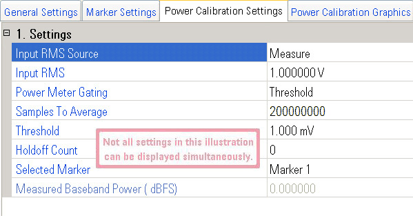
Power Calibration Considerations
|
Choices: Measure, Use Last RMS, User Entered
Default Value: Measure
Identifies where the PXB gets the RMS voltage value of the input waveform to ensure the correct amplitude of the waveform is at the output of the external instrument. This RMS voltage value is used to calibrate the power of the system (the PXB and the signal generator) when the power calibration is performed.
|
|
An incorrect Input RMS entry will result in an incorrect output level and an incorrect SNR if AWGN is enabled. |
Measure
This choice pre-plays the input waveform and measures the waveform's RMS
voltage with a power meter that is located at the output of the baseband
generator block. The measured RMS voltage is for the power calibration.
When Measure is selected, the Power Meter Gating setting selects whether
a voltage threshold or a marker is used to identify the portions of the
waveform that will be measured.
Use Last RMS
This choice uses the last RMS voltage (either measured or user entered)
for the power calibration. This is very useful when you are "re-playing"
an input signal that was measured because it saves you the time of re-measuring
the signal.
User Entered
This choice allows you to enter the RMS voltage of the input waveform directly.
If you know the waveform's RMS voltage, entering the voltage is quicker
than measuring the waveform.
Range:
0 to 1.414214 V
Default Value: 1.000000 V
Resolution: 1 µV
Dependency: Displayed only when RMS Source is set to User Entered
Sets the known RMS voltage of the input waveform.
Choices:
Threshold, Marker
Default Value: Threshold
Dependency: Displayed only when RMS Source is set to Measure
Selects the method used to identify which input waveform samples are measured when determining the waveform's RMS voltage. An illustration showing both Power Meter Gating choices can be viewed at Power Calibration Graphics.
Threshold
This choice allows you to set a threshold level to tell the PXB when to
measure the input waveform. When the waveform voltage level meets or exceeds
the threshold level, the voltage for the waveform sample is used to determine
the waveforms RMS voltage. When the waveform voltage level is less than
the threshold level, the voltage for the waveform sample is not used to
determine the waveform's RMS voltage.
Marker
This choice uses a marker, identified by the Marker selection, to tell the PXB when to measure the
input waveform. When the marker is turned on, the voltage for the waveform
sample is used to determine the waveform's RMS voltage. When the marker
is turned off, the voltage for the waveform sample is not used to determine
the waveform's RMS voltage. The marker criteria is set using the Marker Settings tab.
Range: 4 to 549755813887
Default Value: 200000000
Resolution: Rounds off to the nearest power of 2 (2n)
Dependency: Displayed only when RMS Source is set to Measure
Specifies the number of samples (at 200 MSa/s internally resampled rate) that are averaged when calculating the RMS voltage. When the input waveform is measured, the PXB measures the specified number of samples that meet the criteria set by the threshold or marker settings and then uses these sample RMS voltage values to calculate the mean RMS voltage for the subsequent power calibration.
The default setting of 200000000 generally provides good accuracy for measuring bursted input signals. Adjust this value as needed for your signal.
Range:
0 to 1.414214 V
Default Value: 0.001 V
Resolution: 10 µV
Dependency: Displayed only when Power Meter Gating is set to Threshold
Defines the threshold voltage used to determine when the input waveform sample voltage measurement is used to determine the waveform's RMS voltage. An illustration showing an example of using a threshold can be viewed at Power Calibration Graphics.
Range:
0 to 65,535 (216–1)
Default Value: 0
Resolution: 1
Dependency: Displayed only when Power Meter Gating is set to Threshold
Allows you to specify the number of consecutive input waveform samples that must meet or exceed the threshold voltage level before the input waveform sample is used to determine the waveform's RMS voltage. If the number of consecutive waveform samples is not met, the sample voltages are not used. This setting is useful if the waveform has an inconsistent structure or to eliminate glitches. An illustration showing an example of using Holdoff Sample Count can be viewed at Power Calibration Graphics.
Choices:
Marker 1, Marker 3, Marker 4
Default Value: Marker 1
Dependency: Displayed only when Power Meter Gating is set to Marker
Selects which marker is used to define when the input waveform is measured to determine the RMS voltage. An illustration showing an example of using a marker for power meter control can be viewed at Power Calibration Graphics.
Displays the measured baseband power at the IO input. The value is displayed in dBFS (dB, relative to full-scale voltage of 1.4142V).
General
Settings
Marker Settings
Power Calibration Graphics