The PXB uses the signal analyzer as a down converter for RF-to-RF in the PXB's external input (ext in) configurations. The PXB controls the signal analyzer only in the signal analyzer's IQ Analyzer (Basic) mode. The PXB sets the signal analyzer to a known state, so only the signal analyzer settings displayed in the PXB user interface are safe to change. Making other signal analyzer setting changes may be coupled with the known state of the signal analyzer as the PXB attempts to control it and could deliver undesirable results.
When a configuration that uses a signal analyzer is loaded or recalled, the PXB attempts to establish communication with the signal analyzer when the configuration is loaded. If communication is not established with the signal analyzer at that time, the PXB will attempt to establish communication:
If the Preset or Test Connection buttons are selected
When the Play button is selected (if the PXB is still not connected to the signal analyzer when the Play button is pressed, the PXB generates a warning message)
When the PXB establishes communication with the signal analyzer, the PXB:
Sets the signal analyzer to the IQ Analyzer (Basic) mode
Performs a Mode Preset on the analyzer
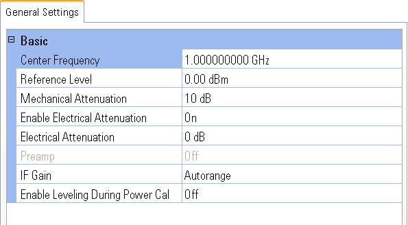
Downloads its Signal Analyzer user interface settings to the analyzer
|
|
Programming Control of the Signal Analyzer The PXB controls the signal analyzer only through its user interface, so controlling the signal analyzer programmatically must be done directly. Refer to the signal analyzer's programming guide for details. When a configuration is loaded or recalled, the PXB presets the signal analyzer and then sets it to IQ Analyzer (Basic) mode. So, when the system is being controlled programmatically, perform the tasks in the order listed.
Following these steps in this order ensures that the PXB does not overwrite any SCPI commands sent to the signal analyzer. |
Optimizing the MXA provides a procedure and discussion of how to maximize the MXA's dynamic range for use as an input to the PXB.
Range: Log Scale: –170 to +30 dBm
Default: 0.00 dBm
Resolution: 0.01 dB
controls the vertical (y-axis) placement of the signal on the signal analyzer display. The reference level is the amplitude power or voltage represented by the top graticule on the display. Changing the value of the reference level changes the absolute amplitude level of the top graticule line. Setting the reference level to a value slightly above the expected maximum power level of the signal analyzer's input signal provides optimum results.
Range: 0 to 70 dB
Default: 10 dB
Resolution: 2 dB
Sets the mechanical attenuation value to pre-adjust the input signal for minimum clipping. This attenuates the input so it does not over-drive the analyzer (thus preventing IF overload). For more information, refer to N9060A IQ Analyzer Mode User's and Programmer's Reference (N9060-90018).
|
|
Setting of the signal analyzer input attenuation to the correct level is critical. The input attenuation should be set to the minimum possible without over driving the analog-to-digital converter (ADC). When the ADC is over driven, the signal is clipped and distorted by the MXA before it arrives at the PXB. |
Choices: On, Off
Default: On
Turns the electrical attenuation on or off. When Electrical Attenuation is enabled, the following transitions occur:
Mechanical Attenuation is initialized to 10 dB (this is its optimal performance setting). You can then set it with the numeric keypad, step keys, or RPG, from the front panel keys on the PXB. It behaves as it normally would in manual mode.
The state of Mechanical Attenuation is saved and restored when the electrical attenuation is once again disabled.
The Electrical Attenuation is set to 10 dB less than the previous value of the Mechanical Attenuator, within the range limits of the 0 to 24 dB of attenuation.
Controls the signal analyzer's internal preamps. Turning on the preamp gives a better noise figure, but a poorer dynamic range. You can optimize this setting for your particular measurement.
For more information on the preamp functionality, refer to N9060A IQ Analyzer Mode User's and Programmer's Reference (N9060-90018).