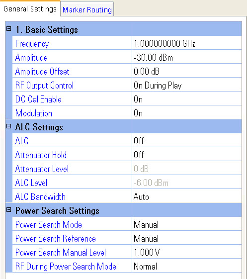
The signal generators that are supported are the Agilent N5182A MXG Signal Generator and the Agilent E4438C ESG signal generator. The E4438C ESG has one setting, ALC Bandwidth, that is not supported by the N5182A MXG.
Signal generator settings in the PXB user interface are automatically loaded to the signal generator. However, if you make changes to the front panel of the signal generator, select the Update From Inst button to load relevant changes from the signal generator to the PXB.
|
|
The PXB will over write the following properties on this panel and in the signal generator when necessary: |
|
|
|
The PXB controls some very specific signal generator properties during configuration, power calibration, and during a play. Not all of these properties are displayed on this panel. |
Range: Depends on connected Signal Generator Frequency Option
Default: 1 GHz
Resolution: 0.001 Hz
Sets the signal generator's RF output frequency.
Range: Depends on the connected signal generator
Default: –30 dBm
Resolution: 0.01 dB
Sets the signal generator's RF output amplitude. When Attenuator Hold is on, this setting is also coupled to ALC Level and the attenuator values.
Range: –200 to 200
dB
Default: 0 dB
Resolution: 0.01 dB
Sets a value that is applied to the signal generator's displayed amplitude. The amplitude of the signal generator's RF Output is not changed.
The amplitude offset may be overwritten by the PXB to ensure the desired output power from the signal generator. Do not change this value without complete understanding of the PXB power calibration.
Choices: Always Off, Always On, On During
Play
Default: On During Play
Controls the state of the signal generator's RF output.
Always Off
This selection turns off the signal generator RF output. The status of
the PXB Play function has no effect on the RF output.
Always On
This selection turns on the signal generator RF output. The status of the
PXB Play function has no effect on the RF output.
On During Play
This selection turns on the signal generator RF output when the PXB is
playing a signal and turns the RF output off when the signal is no longer
playing.
Choices: On, Off
Default: On
Enables or disables the signal generator's DC Cal function. When enabled, the signal generator performs a DC calibration at the beginning of each playback.
Choices: On, Off
Default: On
Enables or disables the signal generator's modulation of the output carrier signal by an active modulation format.
Choices: On, Off
Default: Off
Enables or disables the signal generator's automatic leveling control (ALC).
When generating a non-faded signal, the signal generator normally uses
an ALC circuit to control the power. A detector senses the output power,
compares it to the desired reference level, and feeds back the difference
to an RF modulator to correct any error.
On
This selection is the mode of level control; the average carrier level
is constantly monitored and controlled by the ALC. Its purpose is to hold
output power at its desired level in spite of drift due to temperature
and time.
Off
This selection is used for cases when the RF level cannot be accurately
determined by sensing its average level. With ALC off, there is no closed-loop
feedback to sense the RF level and correct for errors so a Power Search
performed to calibrate the RF level.
For most PXB configurations, it is best to leave ALC off. When the configuration is using fading, summing, or AWGN it is best to ensure that ALC is off, since the ALC counteracts the power effects of turning these features on/off while the system is playing. The ALC state is automatically turned off when a power calibration is performed for configurations with faders.
Choices: On, Off
Default: Off
Prevents the attenuator level from changing.
With Attenuator Hold turned on, the changes to the signal generator's power level are only done using the ALC: the attenuator will not change its level. Attenuator Level must be disabled before a power calibration. The attenuator hold circuitry is coupled with the Attenuator Level and ALC Level settings. The Attenuator Hold function, when enabled, prevents the attenuator from switching levels.
Range: Depends on the connected signal generator
Default Value: 0 dB
Resolution: Depends on the connected signal generator
Dependency: Active only when Attenuator Hold is set to On
Sets the signal generator's attenuator level in dB. The signal generator's output power is the difference between the ALC Level and the Attenuator Level.
Range: Depends on the connected signal generator
Default: 5 dBm
Resolution: 0.01 dB
Dependency: Active only when Attenuator Hold is set to On
Sets the ALC power level at which the signal generator's RF power is held constant.
Choices: Auto, 100 Hz, 1 kHz, 10 kHz
Default: Auto
Dependency: Displayed only when ESG-C is selected as the External Instrument
Sets the ALC loop bandwidth for which the ALC circuit will provide corrections. The Auto selection automatically selects the optimized bandwidth for the current signal setup. If Auto does not provide the expected performance, you may select from 100 Hz, 1 kHz, or 10 kHz. By trying these choices, you can optimize your ALC loop bandwidth by balancing between is improved error vector magnitude (EVM) performance of the narrow bandwidth selection and the faster switching speed afforded by the wide bandwidth selection.
This selection may be changed even while the waveform is playing.
Power Search is a calibration routine which is used to set an accurate RF level with ALC off. During a power-search cycle, the ALC system is temporarily switched on just long enough to determine (and store) the ALC modulator value which gives the correct RF level. The gain of the RF system is then held constant, so the RF level is accurate for long periods even though there is no closed-loop feedback.
Choices: Auto, Manual, Span
Default: Manual, Auto (some MXGs, see note below)
Dependency: Active only when ALC is set to Off
Sets the method for starting the power search routine. The PXB disables the ALC and sets this mode to Manual for the ESG and sets it to Auto for the MXG whenever fading is present in the configuration. This is executed automatically during a power calibration.
Auto
This choice performs a power search automatically any time the user changes
RF frequency or amplitude.
Span
This choice performs a power search over a range of frequencies that you
define. The power search corrections are stored and used when the signal
generator is tuned within the defined range. This is useful for applications
requiring fast frequency changes. While this selection is available within
the signal generator, it has no practical use when controlled by the PXB.
Manual
This choice disables the automatic power search and you must manually execute
a power search to correct the power level.
|
|
Manual Power Search Mode is only available on connected MXG instruments beginning with serial number 4818 or greater, or with serial number less than 4818 that have Option 099 installed. |
|
|
If ALC on the signal generator is turned off or if a Fader block is in the loaded configuration, a power search is performed when the Calibrate Power function is initiated. This power search will overwrite the current Power Search Mode selection. |
Choices: Fixed, Manual, Modulation, RMS
Default: Manual, Modulation (MXGs using Analog I/Q)
Dependency: Active only when ALC is set to Off
Selects RMS, Fixed, Manual, or Modulated as the power search reference.
Fixed
This choice sets the power search process to use a 1.0V reference as the
search reference.
Manual
This choice sets the power search process to use the DC bias voltage value
specified in Power Search Manual Level
as the search reference.
Modulation
This choice sets the power search process to use the AC bias from the actual
modulating signal as the search reference.
RMS
This choice sets the power search process to use the DC bias equivalent
to the value derived from the file header or the calculated value from
the current I/Q data as the search reference.
This selection may be changed even while the waveform is playing.
|
|
If ALC on the Signal Generator is turned off or if a Fader block is in the loaded configuration, a power search is performed when the Calibrate Power function is initiated. This power search could overwrite the current Power Search Reference selection. |
Range: 0.0 to 1.414 V
Default: 1.0 V
Resolution: 0.001 V
Dependency: Active only when Power Search Reference is set to Manual
Sets the power search DC bias voltage value a for manual power search.
|
|
If ALC on the Signal Generator is turned off or if a Fader block is in the loaded configuration, a power search is performed when the Calibrate Power function is initiated. This power search will overwrite the current Power Search Manual Level setting. |
Choices: Normal, Minimum
Default: Normal
Dependency: Active only when ALC is set to Off
Selects a minimum or normal RF power level for the power search.
Normal
This choice performs the power search without the protection described
in Minimum.
Minimum
This choice sets the internal step attenuator to its maximum setting during
power search to protect power-sensitive circuits.
This selection may be changed even while the waveform is playing.
|
|
If ALC on the Signal Generator is turned off or if a Fader block is in the loaded configuration, a power search is performed when the Calibrate Power function is initiated. This power search could overwrite the current RF During Power Search Mode setting. |