This capability requires license model E7653APPC.
This topic describes the RF Output > Corrections/De-embedding screen, where you can configure and apply external corrections for your test setup.
Center Frequency Corrections Only
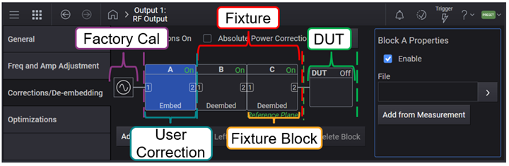
The instrument has the capability to extend the Reference Plane beyond the factory calibrated RF Output port. The Reference Plane can be extended via Corrections and/or S-parameter de-embedding.
Up to four stages of correction and de-embedding are available. These stages are referred to as blocks and are labeled as Block A, B, C, and D. For SCPI commands, block A=1, B=2, and so on.
The following table lists the available correction and de-embedding components for your test setup.
| Component | Purpose | Supported File Format(s) |
|---|---|---|
| Factory Cal |
Directly measured correction data created during the factory manufacturing process or annual calibration. |
N/A |
| Block A |
User correction data applied on top of the Factory Cal. For this block, you can:
|
.csv .uflat (for compatibility with other Keysight Technologies signal generators) |
| Block B |
De-embedding of fixtures including cables, connectors, and other passive components between the instrument and DUT to remove the effects of these test fixtures from the measurement results. Individual fixture blocks represent different fixture elements in your test setup. Calculated correction data for the sum of Blocks B, C, and/or D is applied on top of the Block A and/or Factory Cal. Prior to the software version A.14.00, only the S21 data of the fixture was used for correction. With software version A.14.00 or later, the S11 and S21 data of the fixture are used for correction. Due to this difference in the S-parameters used for correction in these software versions, the calculated correction data may vary for these software versions.
To apply corrections for a fixture, you can:
|
.s2p |
| Block C | ||
| Block D | ||
| DUT |
Compensation for the instrument to DUT mismatch. For this block, you can:
Requires Option V08. |
.s1p |
Enables or disables the user-flatness corrections.
|
GUI Location |
RF Output > Corrections/De-embedding > Corrections On |
|
SCPI Command |
[:SOURce][:RF<channel>]:CORRection[:STATe] ON|OFF|1|0 [:SOURce][:RF<channel>]:CORRection[:STATe]? |
|
SCPI Example |
CORR ON CORR? |
| Notes | Output power may become too high when Corrections/Deembedding fixture's S-parameter includes S21 = 0. |
|
Preset |
0 |
|
State Saved |
Yes |
Ignores the complex response data in measured (block A) or s2p (block B, C, D) data and only applies the absolute power, phase and time corrections.
|
GUI Location |
RF Output > Corrections/De-embedding > Center Frequency Correction Only |
|
SCPI Command |
[:SOURce][:RF<channel>]:CORRection:CFConly[1]|2[:STATe] ON|OFF|0|1 [:SOURce][:RF<channel>]:CORRection:CFConly[1]|2[:STATe]? |
|
SCPI Example |
For Block A: CORR:CFC ON CORR:CFC? For Block B, C, D CORR:CFC2 ON CORR:CFC2? |
|
Preset |
0 |
|
State Saved |
Yes |
| Backwards Compatibility SCPI |
[:SOURce][:RF<channel>]:CORRection:APConly[:STATe] |
| Backwards Compatibility Notes |
Alias [:SOURce][:RF<channel>]:CORRection:APConly[:STATe] to [:SOURce][:RF<channel>]:CORRection:CFConly[1][:STATe]; [:SOURce][:RF<channel>]:CORRection:CFConly2[:STATe] See Also - DUT Reflection Coefficient > Center Frequency Corrections Only |
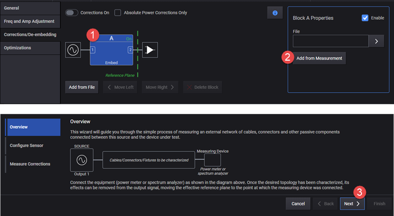
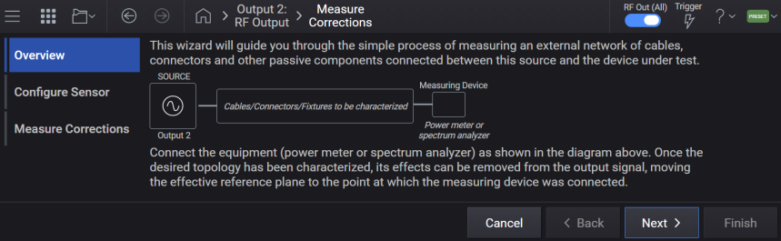
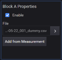
You can use the Block A properties > Add from Measurement button to access the Measure Corrections wizard. Using this wizard, you can configure and run the user correction measurement. The correction data generated from this measurement is saved to a .csv file. This file is then used as the correction file.
The subsections below describe the SCPI commands available to configure and run the user correction measurement.
SCPI commands defined in this section can be used to set up Correction measurements and Power Sensors used. In the user interface, these settings are included in the RF Output block's, Corrections/De-embedding block setup, when the Add from Measurement button is selected.
Supported measurement devices are as follows.
Keysight U8480 Series USB Thermocouple Power Sensor
Keysight U2000 Series USB Sensors
Including:
U2000 Series USB Power Sensors:
U8487A-CFG007
U8485A-CFG006
U2000A
U2001A
U2002A
U2004A
U2000B
U2001B
U2000H
U2001H
U2002H
U2021XA/22XA
U2041XA/42XA/43XA/44XA
U2051XA/52XA/53XA/54XA/55XA/56XA/57XA
U2061XA/62XA/63XA/64XA/65XA/66XA/67XA
X-Series Signal Analyzers:
N9000A/B
N9010A/B
N9020A/B
N9030A/B
N9040B
N9041B
M90XA
N9021B
Enables the Device List to be the sole method of specifying a Spectrum Analyzer or Power Meter to be used for Correction Measurement.
To configure external devices in the Device List, see Device List.
|
GUI Location |
RF Output > Corrections/De-embedding > Add from Measurement > Configure Sensor > Power Measurement Device > Use Device List (checkbox) |
|
SCPI Command |
[:SOURce][:RF<channel>]:CORRection:DLISt ON|OFF|1|0 [:SOURce][:RF<channel>]:CORRection:DLISt? |
|
SCPI Example |
RF3:CORR:DLIS ON RF3:CORR:DLIS? |
|
Preset |
OFF |
|
State Saved |
Yes |
|
Choices |
ON | OFF | 1 | 0 |
Specifies a Power Meter or a Spectrum Analyzer from the Device List for user Correction Measurement. Note that the reference clock must be locked between the signal generator and Spectrum Analyzers.
To configure external devices in the Device List, see Device List.
|
GUI Location |
RF Output > Corrections/De-embedding > Add from Measurement > Configure Sensor > Power Measurement Device > Use Device List (selected) > Configure Device |
|
SCPI Command |
[:SOURce][:RF<channel>]:CORRection:DEVice <name string> [:SOURce][:RF<channel>]:CORRection:DEVice? |
|
SCPI Example |
RF3:CORR:DEV "myDevice" RF3:CORR:DEV? |
|
Notes |
If the specified device does not exist in the Device List, an error will be raised: -220,"Parameter error; Specified device does not exist" If the specified device is not a Spectrum Analyzer or Power Meter, an error will be raised: -220,"Parameter error; Correction Measurement requires a Spectrum Analyzer or Power Meter device type" |
|
Couplings |
If the device currently selected from the Device List is removed, this setting will default to NONE Value will only be utilized by hardware when Use Device List for Correction Measurement is set to ON. |
|
Preset |
NONE |
|
State Saved |
Yes |
Selects the hardware type used in the user correction measurement when the Device List is not being used.
PMETer: Flatness calibration is done with a power meter.
SANalyzer: Flatness calibration is done with a spectrum analyzer. Note that the reference clock must be locked between the signal generator and the spectrum analyzer.
|
GUI Location |
RF Output > Corrections/De-embedding > Add from Measurement > Configure Sensor > Power Measurement Device |
|
SCPI Command |
[:SOURce][:RF<channel>]:CORRection:PMDevice PMETer|SANalyzer [:SOURce][:RF<channel>]:CORRection:PMDevice? |
|
SCPI Example |
CORR:PMD PMET CORR:PMD? |
|
Couplings |
Value will only be utilized by the instrument when Use Device List for Correction Measurement is set to OFF. |
|
Preset |
PMETer |
|
State Saved |
Yes |
|
Choices |
Power Meter | Spectrum Analyzer |
Sets the start frequency for the user flatness calibration step array.
|
GUI Location |
RF Output > Corrections/De-embedding > Add from Measurement > Start Frequency |
|
SCPI Command |
[:SOURce][:RF<channel>]:CORRection:FLATness:STEP:STARt <freq> [:SOURce][:RF<channel>]:CORRection:FLATness:STEP:STARt? |
|
SCPI Example |
CORR:FLAT:STEP:STAR 1GHz CORR:FLAT:STEP:STAR? |
|
Couplings |
Coupled to Stop Frequency. If Start Frequency goes above Stop Frequency, Stop Frequency is automatically adjusted to Start Frequency. |
|
Preset |
1 GHz |
|
State Saved |
Yes |
|
Min |
For |
|
Max |
For
|
|
Resolution |
For |
Sets the stop frequency for the user flatness calibration step array.
|
GUI Location |
RF Output > Corrections/De-embedding > Add from Measurement > Stop Frequency |
|
SCPI Command |
[:SOURce][:RF<channel>]:CORRection:FLATness:STEP:STOP <freq> [:SOURce][:RF<channel>]:CORRection:FLATness:STEP:STOP? |
|
SCPI Example |
CORR:FLAT:STEP:STOP 1GHz CORR:FLAT:STEP:STOP? |
|
Couplings |
Coupled to Start Frequency. If Stop Frequency goes below Start Frequency, Start Frequency is automatically adjusted to Stop Frequency. |
|
Preset |
2 GHz |
|
State Saved |
Yes |
|
Min |
For |
|
Max |
For
|
|
Resolution |
For |
Defines the number of points in the user flatness calibration step array.
|
GUI Location |
RF Output > Corrections/De-embedding > Add from Measurement > Number of Steps |
|
SCPI Command |
[:SOURce][:RF<channel>]:CORRection:FLATness:STEP:POINts <integer> [:SOURce][:RF<channel>]:CORRection:FLATness:STEP: POINts? |
|
SCPI Example |
CORR:FLAT:STEP:POIN 2 CORR:FLAT:STEP:POIN? |
|
Preset |
10 |
|
State Saved |
Yes |
|
Min |
2 |
|
Max |
10000 |
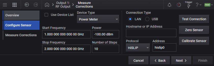
Sets the power meter properties when Power Meter is the selected Power Measurement Device.
Sets the type of control connection for communication using the external power meter for user flatness calibration.
|
HISLip |
Enables the power meter for HiSlip control through the signal generator |
|
SOCKets |
Enables the power meter for sockets LAN control through the signal generator. |
|
USB |
Enables the power meter for USB control through the signal generator. |
|
GUI Location |
RF Output > Corrections/De-embedding > Add from Measurement > Configure > Connection Type > LAN, HiSLIP, Socket) or USB |
|
SCPI Command |
[:SOURce][:RF<channel>]:CORRection:PMETer:COMMunicate:TYPE SOCKets|USB|HISLip [:SOURce][:RF<channel>]:CORRection:PMETer:COMMunicate:TYPE? |
|
SCPI Example |
CORR:PMET:COMM:TYPE SOCK CORR:PMET:COMM:TYPE? |
|
Notes |
The settings enabled by this command are not affected by a signal generator power-on, preset, or *RST. Value will only be utilized by the instrument when Use Device List for Correction Measurement is set to OFF. |
|
Preset |
SOCKets |
|
State Saved |
No |
|
Choices |
Socket | USB | HiSlip |
Sets the internet protocol (IP) address for a power meter that is controlled by the signal generator for user flatness calibration. If connecting to a GPIB power meter through a LAN-GPIB gateway, this command sets the IP address of the gateway.
|
GUI Location |
RF Output > Corrections/De-embedding > Add from Measurement > Configure > Connection Type > Connection Type LAN > Set LAN IP Address |
|
SCPI Command |
[:SOURce][:RF<channel>]:CORRection:PMETer:COMMunicate:LAN:IP <string> [:SOURce][:RF<channel>]:CORRection:PMETer:COMMunicate:LAN:IP? |
|
SCPI Example |
CORR:PMET:COMM:LAN:IP "192.168.1.5" CORR:PMET:COMM:LAN:IP? |
|
Notes |
The settings enabled by this command are not affected by signal generator power-on, preset, or *RST. Ensure that the power meter IP address is different from the signal generator address. Value will only be utilized by the instrument when Use Device List for Correction Measurement is set to OFF. |
|
State Saved |
No |
Specifies the HiSLIP device name for a power meter that is being controlled by the signal generator for user flatness calibration. If connecting directly to the power meter, enter the name as specified in your power meter documentation.
|
GUI Location |
RF Output > Corrections/De-embedding > Add from Measurement > Configure > Connection Type LAN > HiSLIP > Remote Name |
|
SCPI Command |
[:SOURce][:RF<channel>]:CORRection:PMETer:COMMunicate:HISLip:DEVice <string> [:SOURce][:RF<channel>]:CORRection:PMETer:COMMunicate:HISLip:DEVice? |
|
SCPI Example |
CORR:PMET:COMM:HISL:DEV "hslip1" CORR:PMET:COMM:HISL:DEV? |
|
Notes |
The settings enabled by this command are not affected by signal generator power-on, preset, or *RST. Value will only be utilized by the instrument when Use Device List for Correction Measurement is set to OFF. |
|
Preset |
hislip0 |
|
State Saved |
No |
Selects the USB device to be used for user flatness calibration. The query returns the USB device identification.
|
GUI Location |
RF Output > Corrections/De-embedding > Add from Measurement > Configure > Connection Type USB > Device |
|
SCPI Command |
[:SOURce][:RF<channel>]:CORRection:PMETer:COMMunicate:USB:DEVice <string> [:SOURce][:RF<channel>]:CORRection:PMETer:COMMunicate:USB:DEVice? |
|
SCPI Example |
CORR:PMET:COMM:USB:DEV "instr0" CORR:PMET:COMM:USB:DEV? |
|
Notes |
The settings enabled by this command are not affected by signal generator power-on, preset, or *RST. Value will only be utilized by the instrument when Use Device List for Correction Measurement is set to OFF. |
|
State Saved |
No |
Remote command only.
Returns a listing of all connected USB devices.
|
SCPI Command |
[:SOURce][:RF<channel>]:CORRection:PMETer:COMMunicate:USB:LIST? |
|
SCPI Example |
CORR:PMET:COMM:USB:LIST? |
|
Notes |
The settings enabled by this command are not affected by signal generator power-on, preset, or *RST. |
|
State Saved |
No |
Sets the IP port number on the power meter that is controlled by the signal generator for users flatness calibration.
|
5025 |
Standard mode. The command enables standard mode for simple programming. |
|
5024 |
Telnet mode. The command enables the telnet SCPI service for programming. |
|
GUI Location |
RF Output > Corrections/De-embedding > Add from Measurement > Configure > Connection Type LAN > Protocol set to Socket > Port Number |
|
SCPI Command |
[:SOURce][:RF<channel>]:CORRection:PMETer:COMMunicate:LAN:PORT <integer> [:SOURce][:RF<channel>]:CORRection:PMETer:COMMunicate:LAN:PORT? |
|
SCPI Example |
CORR:PMET:COMM:LAN:PORT 5025 CORR:PMET:COMM:LAN:PORT? |
|
Notes |
The settings enabled by this command are not affected by signal generator power-on, preset, or *RST. Value will only be utilized by the instrument when Use Device List for Correction Measurement is set to OFF. |
|
Preset |
5025 |
|
State Saved |
No |
Selects the channel setting on the external power meter used for calibration from the Device List.
|
GUI Location |
RF Output > Corrections/De-embedding > Add from Measurement > Next > Use Device List (checked) > Configure Device > (select or add a device) > Power Meter Channel (drop-down menu) |
|
Notes |
The setting enabled by this command is not affected by signal generator power-on, preset, or *RST. |
|
Preset |
Channel 1 |
|
Range |
Channel 1 | Channel 2 | Channel 3 | Channel 4 |
|
State Saved |
No |
Calibrates the connected power meter. This is an immediate action.
|
GUI Location |
RF Output > Corrections/De-embedding > Add from Measurement > Next > Calibrate Sensor |
|
SCPI Command |
[:SOURce][:RF<channel>]:CORRection:PMETer:CALibrate |
|
SCPI Example |
CORR:PMET:CAL |
Calibrates the connected power meter from the Device List. This is an immediate action.
|
GUI Location |
RF Output > Corrections/De-embedding > Add from Measurement > Next > Use Device List (checked) > Configure Device > (select or add a device) > Calibrate Sensor |
|
SCPI Command |
[:SOURce][:RF<channel>]:CORRection:PMETer:CALibrate:DLISt <string> |
|
SCPI Example |
CORR:PMET:CAL:DLIS "myDevice" |
|
Notes |
If the specified device does not exist in the Device List, an error will be raised: -220,"Parameter error; Specified device does not exist" If the specified device is not a Power Meter, an error will be raised: -220,"Parameter error; Power Meter Calibrate Sensor requires a Power Meter device type" |
Zeroes the connected power meter. This is an immediate action.
|
GUI Location |
RF Output > Corrections/De-embedding > Add from Measurement > Configure > Zero Sensor |
|
SCPI Command |
[:SOURce][:RF<channel>]:CORRection:PMETer:ZERO |
|
SCPI Example |
CORR:PMET:ZERO |
Zeroes the connected power meter from the Device List. This is an immediate action.
|
GUI Location |
RF Output > Corrections/De-embedding > Add from Measurement > Next > Use Device List (checked) > Configure Device > (select or add a device) > Zero Sensor |
|
SCPI Command |
[:SOURce][:RF<channel>]:CORRection:PMETer:ZERO:DLISt <string> |
|
SCPI Example |
CORR:PMET:ZERO:DLIS "myDevice" |
|
Notes |
If the specified device does not exist in the Device List, an error will be raised: -220,"Parameter error; Specified device does not exist" If the specified device is not a Power Meter, an error will be raised: -220,"Parameter error; Power Meter Zero Sensor requires a Power Meter device type" |
Sets the spectrum analyzer properties when Spectrum Analyzer is the selected Power Measurement Device.
Sets the type of control connection for communication with the external spectrum analyzer for user flatness calibration.
|
GUI Location |
RF Output > Corrections/De-embedding > Add from Measurement > Configure > Connection Type > LAN, HiSLIP, Socket) or USB |
|
HISLip |
Enables the spectrum analyzer for HiSlip control through the signal generator. |
|
SOCKets |
Enables the spectrum analyzer for sockets LAN control through the signal generator. |
|
USB |
Enables the spectrum analyzer for USB control through the signal generator. |
|
SCPI Command |
[:SOURce][:RF<channel>]:CORRection:SANalyzer:COMMunicate:TYPE SOCKets |USB|HISLip [:SOURce][:RF<channel>]:CORRection:SANalyzer:COMMunicate:TYPE? |
|
SCPI Example |
CORR:SAN:COMM:TYPE SOCK CORR:SAN:COMM:TYPE? |
|
Notes |
The setting enabled by this command is not affected by signal generator power-on, preset, or *RST. Value will only be utilized by the instrument when Use Device List for Correction Measurement is set to OFF. |
|
Preset |
SOCKets |
|
State Saved |
No |
|
Choices |
Socket | USB | HiSlip |
Sets the internet protocol (IP) address for a spectrum analyzer that is controlled by the signal generator for user flatness calibration. If connecting to a GPIB spectrum analyzer through a LAN-GPIB gateway, this command sets the IP address of the gateway.
|
GUI Location |
RF Output > Corrections/De-embedding > Add from Measurement > Configure > Connection Type > LAN > Hostname or IP Address |
|
SCPI Command |
[:SOURce][:RF<channel>]:CORRection:SANalyzer:COMMunicate:LAN:IP <string> [:SOURce][:RF<channel>]:CORRection:SANalyzer:COMMunicate:LAN:IP? |
|
SCPI Example |
CORR:SAN:COMM:LAN:IP "192.168.1.5" CORR:SAN:COMM:LAN:IP? |
|
Notes |
The setting enabled by this command is not affected by signal generator power-on, preset, or *RST. Ensure that the spectrum analyzer IP address is different from the signal generator address. Value will only be utilized by the instrument when Use Device List for Correction Measurement is set to OFF. |
|
State Saved |
No |
Enter a HiSlip device name for a spectrum analyzer that is being controlled by the signal generator for user flatness calibration. If connecting directly to the spectrum analyzer, enter the name as specified on your spectrum analyzer documentation.
|
GUI Location |
RF Output > Corrections/De-embedding > Add from Measurement > Configure > Connection Type > LAN > HiSLIP > Address |
|
SCPI Command |
[:SOURce][:RF<channel>]:CORRection:SANalyzer:COMMunicate:HISLip:DEVice <string> [:SOURce][:RF<channel>]:CORRection:SANalyzer:COMMunicate:HISLip:DEVice? |
|
SCPI Example |
CORR:SAN:COMM:HISL:DEV "instr0" CORR:SAN:COMM:HISL:DEV? |
|
Notes |
The setting enabled by this command is not affected by signal generator power-on, preset, or *RST. Value will only be utilized by the instrument when Use Device List for Correction Measurement is set to OFF. |
|
Preset |
hislip0 |
|
State Saved |
No |
Selects the USB device to be used for user flatness calibration. The query returns the USB device identification.
|
GUI Location |
RF Output > Corrections/De-embedding > Add from Measurement > Configure > Connection Type > USB > Device |
|
SCPI Command |
[:SOURce][:RF<channel>]:CORRection:SANalyzer:COMMunicate:USB:DEVice <string> [:SOURce][:RF<channel>]:CORRection:SANalyzer:COMMunicate:USB:DEVice? |
|
SCPI Example |
CORR:SAN:COMM:USB:DEV "instr0" CORR:SAN:COMM:USB:DEV? |
|
Notes |
The setting enabled by this command is not affected by signal generator power-on, preset, or *RST. Value will only be utilized by the instrument when Use Device List for Correction Measurement is set to OFF. |
|
State Saved |
No |
Sets the spectrum analyzer's IP port number that is controlled by the signal generator for users flatness calibration.
|
GUI Location |
RF Output > Corrections/De-embedding > Add from Measurement > Configure > Connection Type > LAN > Protocol set to Socket > Port |
|
5025 |
Standard mode. The command enables standard mode for simple programming. |
|
5024 |
Telnet mode. The command enables the telnet SCPI service for programming. |
|
SCPI Command |
[:SOURce][:RF<channel>]:CORRection:SANalyzer:COMMunicate:LAN:PORT <integer> [:SOURce][:RF<channel>]:CORRection:SANalyzer:COMMunicate:LAN:PORT? |
|
SCPI Example |
CORR:SAN:COMM:LAN:PORT 5025 CORR:SAN:COMM:LAN:PORT? |
|
Notes |
The setting enabled by this command is not affected by signal generator power-on, preset, or *RST. Value will only be utilized by the instrument when Use Device List for Correction Measurement is set to OFF. |
|
Preset |
5025 |
|
State Saved |
No |
Remote command only.
Query only. Returns a listing of all connected USB devices.
|
SCPI Command |
[:SOURce][:RF<channel>]:CORRection:SANalyzer:COMMunicate:USB:LIST? |
|
SCPI Example |
CORR:SAN:COMM:USB:LIST? |
|
Notes |
The setting enabled by this command is not affected by signal generator power-on, preset, or *RST. |
|
State Saved |
No |
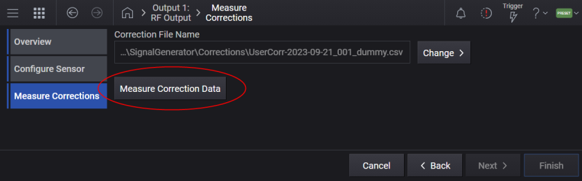
The measured correction data will be saved to the specified file. The file path can be either a full or a relative path. When a relative path is given as file path, it will be based on D:\Users\Instrument\Documents\Keysight\PathWave\SignalGenerator\Corrections. If no file is specified, a file name is automatically created.
This is an overlapped command that initiates the Correction Data measurement. The measurement can be aborted by the Abort command.
Note that the reference clock must be locked between the signal generator and the spectrum analyzer.
|
GUI Location |
RF Output > Corrections/De-embedding > Add from Measurement > Measure Corrections > Measure Correction Data |
|
SCPI Command |
[:SOURce][:RF<channel>]:CORRection:FLATness:CALibrate [<file>] |
|
SCPI Example |
CORR:FLAT:CAL |
|
State Saved |
No |
Aborts the Correction Data measurement.
|
GUI Location |
RF Output > Corrections/De-embedding > Add from Measurement > Measure Corrections > Abort |
|
SCPI Command |
[:SOURce][:RF<channel>]:CORRection:FLATness:CALibrate:ABORt |
|
SCPI Example |
CORR:FLAT:CAL:ABOR |
|
State Saved |
No |
There can be up to four blocks in Corrections Setup. These blocks belong to the following two types.
Block A - This block is for User Corrections (measured correction data). This block comes next to the instrument RF output and always exists.
Block B, C, D - The other block type is a Fixture Block, which represents a fixture between the instrument and DUT. A Fixture Block can be dynamically configured using
To access Block Properties from the GUI, click on the applicable Block- Block A, Block B, Block C or Block D.
Displays or returns the number of Blocks configured for corrections. The maximum number of blocks is four. The minimum number is 1. The first block is for User Corrections and is always present.
|
GUI Location |
RF Output > Corrections/De-embedding |
|
SCPI Command |
[:SOURce][:RF<channel>]:CORRection:BLOCk:COUNt? |
|
SCPI Example |
CORR:BLOC:COUN? |
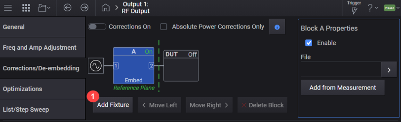
Adds a fixture block at the end of blocks.
|
GUI Location |
RF Output > Corrections/De-embedding > Add Fixture |
|
SCPI Command |
[:SOURce][:RF<channel>]:CORRection:BLOCk:ADD:FIXTure [<file>[,<apply>[,<rport>]]] |
|
SCPI Example |
CORR:BLOC:ADD:FIXT "data.s2p" |
| Notes |
For instruments with Option V08:
For instruments without Option V08:
|
|
State Saved |
No |
Remote command only.
Clears all the blocks except for the first one. The first block is for User Correction and cannot be deleted from the list.
|
SCPI Command |
[:SOURce][:RF<channel>]:CORRection:BLOCk:CLEar:FIXTure |
|
SCPI Example |
CORR:BLOC:CLE:FIXT |
Deletes the specified block. If the specified block doesn’t exist, it issues an error.
There is no SCPI command for this function.
|
GUI Location |
RF Output > Corrections/De-embedding > select applicable Block > Block Properties > Delete Block |
Moves the specified block to the specified position. If the specified block doesn’t exist, it issues an error. If the destination block is smaller than the number of blocks, it issues an error.
There is no SCPI command for this function.
|
GUI Location |
RF Output > Corrections/De-embedding > select applicable Block > Block Properties > Move Left or Move Right |
Sets or queries the correction data file (.csv or .uflat) for Block A and .s2p file for Block B, C, or D.
The default folder location is:
For
Top level of filesystem\Corrections
For Block A (1 in SCPI), the file can be a .uflat file compatible with other Keysight Technologies signal generators, or a .csv file.
The .csv file must be formatted as follows:
The first line is a header.
Each line thereafter must contain three values separated by a comma:
<Frequency in Hz>,<Amplitude in dB>,<Phase in radian>
The lines must be in increasing value of frequency; e.g. the lowest frequency in line 2, the highest frequency in the last line of the file.
|
GUI Location |
RF Output > Corrections/De-embedding > select applicable Block > Block Properties > Change File, current file name |
|
SCPI Command |
[:SOURce][:RF<channel>]:CORRection:BLOCk{1:4}:FILE <"file path"> [:SOURce][:RF<channel>]:CORRection:BLOCk{1:4}:FILE? |
|
SCPI Example |
CORR:BLOC:FILE "FixtureChannel2" |
|
Notes |
Attempting to load a Block A .csv file with four elements in a row, without N7653APPC of subscription date of June 1, 2024 or later, raises the error +703, Feature not supported; N7653APPC with subscription date June 1, 2024, is required. Attempting to load a Block A .csv file with four elements in a row, on an unsupported instrument will raise the error +703, Feature not supported; Correction file cannot contain four elements on {Model}. |
|
Preset |
"" |
|
State Saved |
Yes |
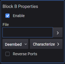
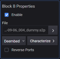
Enables or disables the selected block.
|
GUI Location |
RF Output > Corrections/De-embedding > select applicable Block > Block Properties > Enable |
|
SCPI Command |
[:SOURce][:RF<channel>]:CORRection:BLOCk{1:4}[:STATe] ON|OFF|1|0 [:SOURce][:RF<channel>]:CORRection:BLOCk{1:4}[:STATe]? |
|
SCPI Example |
CORR:BLOC 1 CORR:BLOC? |
|
State Saved |
Yes |
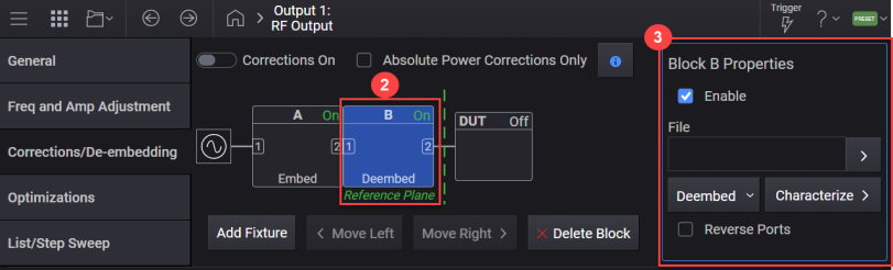
Specifies how the data is applied to the cascaded correction data. When De-embed is selected, the output at the frequency point is adjusted to compensate for the amplitude and phase changes introduced by the block. When Embed is selected, it is adjusted to include them.
|
GUI Location |
RF Output > Corrections/De-embedding > Block B, C, or D > Block Properties > Deembed or Embed |
|
SCPI Command |
[:SOURce][:RF<channel>]:CORRection:BLOCk{2:4}:APPLy DEEMbedding|EMBedding |
|
SCPI Example |
CORR:BLOC2:APPL EMB CORR:BLOC2:APPL? |
|
State Saved |
Yes |
|
Choices |
De-embed | Embed |
Specifies whether the port is reversed or not.
|
GUI Location |
RF Output > Corrections/De-embedding > Block B, C, or D > Block Properties > Reverse Ports |
|
SCPI Command |
[:SOURce][:RF<channel>]:CORRection:BLOCk{2:4}:RPORt ON|OFF|1|0 [:SOURce][:RF<channel>]:CORRection:BLOCk{2:4}:RPORt? |
|
SCPI Example |
CORR:BLOC2:RPOR 1 CORR:BLOC2:RPOR? |
|
State Saved |
Yes |
Enables or disables Snn = 0.
When enabled, the instrument treats reflection S-parameters S11 and S22 as 0.
When disabled, S11 and S22 are normally used from the S-parameter data (no zeroing, default behavior).
|
GUI Location |
RF Output > Corrections/De-embedding > Block B, C, or D > Block Properties > Snn = 0 |
|
SCPI Command |
[:SOURce][:RF<channel>]:CORRection:BLOCk2|3|4:REFLection:ZERO ON|OFF|1|0 [:SOURce][:RF<channel>]:CORRection:BLOCk2|3|4:REFLection:ZERO? |
|
SCPI Example |
CORR:BLOC2:REFL:ZERO 1 CORR:BLOC2:REFL:ZERO? |
| Preset | OFF |
|
State Saved |
Yes |
Requires Option V08
Click the Characterize button to access the Fixture Characterization screen. You can use Fixture Characterization to generate a .s2p file for a fixture using an ECal USB device and use this file as the fixture characterization correction file.
N755x 2-port economy ECal (up to 26.5 GHz)
8509x 2-port RF ECal (up to 9 GHz)
N469x 2-port mW ECal (up to 67 GHz)
N443x 4-port ECal (up to 26.5 GHz)
|
GUI Location |
RF Output > Corrections/De-embedding > Block B, C, or D > Block Properties > Characterize |
The settings shown in the following screen are available for configuring Fixture Characterization correction file.
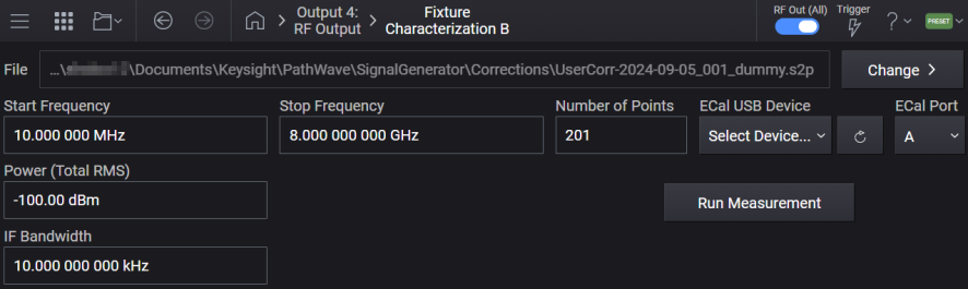
Sets the start frequency for the Fixture Characterization Measurement correction point array. This setting is shared among all blocks.
|
GUI Location |
RF Output > Corrections/De-embedding > Block B, C, or D > Block Properties > Characterize > Start Frequency |
|
SCPI Command |
[:SOURce][:RF<channel>]:CORRection:FIXTure:CHARacterize:STARt <freq> [:SOURce][:RF<channel>]:CORRection:FIXTure:CHARacterize:STARt? |
|
SCPI Example |
RF1:CORR:FIXT:CHAR:STAR 3GHz RF1:CORR:FIXT:CHAR:STAR? |
| Coupling | Coupled to Stop Frequency. If Start Frequency goes above Stop Frequency, Stop Frequency is automatically adjusted to Start Frequency. |
|
Preset |
10 MHz |
|
State Saved |
Yes |
| Min | 9 kHz |
| Max |
With option 503 = 3 GHz With option 506 = 6 GHz With option 508 = 8.5 GHz |
| Resolution | 0.00001 Hz |
Sets the stop frequency for the Fixture Characterization Measurement correction point array. This setting is shared among all blocks.
|
GUI Location |
RF Output > Corrections/De-embedding > Block B, C, or D > Block Properties > Characterize > Stop Frequency |
|
SCPI Command |
[:SOURce][:RF<channel>]:CORRection:FIXTure:CHARacterize:STOP <freq> [:SOURce][:RF<channel>]:CORRection:FIXTure:CHARacterize:STOP? |
|
SCPI Example |
RF1:CORR:FIXT:CHAR:STOP 3GHz RF1:CORR:FIXT:CHAR:STOP? |
| Coupling | Coupled to Start Frequency. If Stop Frequency goes below Start Frequency, Start Frequency is automatically adjusted to Stop Frequency. |
|
Preset |
8 GHz |
|
State Saved |
Yes |
| Min | 9 kHz |
| Max |
With option 503 = 3 GHz With option 506 = 6 GHz With option 508 = 8.5 GHz |
| Resolution | 0.00001 Hz |
Sets the number of points in the Fixture Characterization Measurement correction step array. A frequency spacing of 10 MHz is optimal. This setting is shared among all blocks.
|
GUI Location |
RF Output > Corrections/De-embedding > Block B, C, or D > Block Properties > Characterize > Number of Points |
|
SCPI Command |
[:SOURce][:RF<channel>]:CORRection:FIXTure:CHARacterize:POINts <integer> [:SOURce][:RF<channel>]:CORRection:FIXTure:CHARacterize:POINts? |
|
SCPI Example |
RF1:CORR:FIXT:CHAR:POIN 1000 RF1:CORR:FIXT:CHAR:POIN? |
|
Preset |
201 |
|
State Saved |
Yes |
| Min | 2 |
| Max |
8500 |
|
GUI Location |
RF Output > Corrections/De-embedding > Block B, C, or D > Block Properties > Characterize > Power (Total RMS) |
|
SCPI Command |
Refer to Power (Total RMS) |
Sets the IF bandwidth for the Fixture Characterization Measurement. Reducing the IF receiver bandwidth reduces the effect of random noise on a measurement. Each tenfold reduction in IF bandwidth lowers the noise floor by 10 dB. This setting is shared among all blocks.
|
GUI Location |
RF Output > Corrections/De-embedding > Block B, C, or D > Block Properties > Characterize > IF Bandwidth |
|
SCPI Command |
[:SOURce][:RF<channel>]:CORRection:FIXTure:CHARacterize:BANDwidth <freq> [:SOURce][:RF<channel>]:CORRection:FIXTure:CHARacterize:BANDwidth? |
|
SCPI Example |
RF1:CORR:FIXT:CHAR:BAND 100 RF1:CORR:FIXT:CHAR:BAND? |
|
Preset |
1 kHz |
|
State Saved |
Yes |
| Min | 1 Hz |
| Max |
100 MHz |
| Resolution | 1 Hz |
Query only. Returns a list of all connected USB devices.
|
SCPI Command |
[:SOURce][:RF<channel>]:CORRection:CKIT:COMMunicate:USB:LIST? |
|
SCPI Example |
CORR:CKIT:COMM:USB:LIST? |
|
Notes |
The setting enabled by this command is not affected by signal generator power-on, preset, or *RST. |
|
State Saved |
No |
Specifies the ECal device to use by name for the fixture characterization. The .s2p file for the fixture is generated using the specified ECal device.
See Supported ECal devices for fixture characterization
|
GUI Location |
RF Output > Corrections/De-embedding > Block B, C, or D > Block Properties > Characterize > ECal USB Device |
|
SCPI Command |
[:SOURce][:RF<channel>]:CORRection:CKIT:COMMunicate:USB:DEVice <string> [:SOURce][:RF<channel>]:CORRection:CKIT:COMMunicate:USB:DEVice? |
|
SCPI Example |
CORR:CKIT:COMM:USB:DEV "instr0" CORR:CKIT:COMM:USB:DEV? |
|
Notes |
The setting enabled by this command is not affected by signal generator power-on, preset, or *RST. |
|
State Saved |
No |
Specifies the ECal port to be used for fixture characterization.
|
GUI Location |
RF Output > Corrections/De-embedding > Block B, C, or D > Block Properties > Characterize > ECal port |
|
SCPI Command |
[:SOURce][:RF<channel>]:CORRection:CKIT:PORT A|B|C|D [:SOURce][:RF<channel>]:CORRection:CKIT:PORT? |
|
SCPI Example |
CORR:CKIT:PORT A CORR:CKIT:PORT? |
|
Notes |
The setting enabled by this command is not affected by signal generator power-on, preset, or *RST. |
| Preset | A |
| Range | A|B|C|D |
|
State Saved |
No |
Remote Command - Query only.
Returns the compression level for the connected ECal device.
|
SCPI Command |
[:SOURce][:RF<channel>]:CORRection:CKIT:POWer:COMPression? |
|
SCPI Example |
CORR:CKIT:POW:COMP? |
| Notes | When the connected ECal device is not supported, or no ECal device is connected, this command returns 999 dBm. |
Remote Command - Query only.
Returns the damage level for the connected ECal device.
|
SCPI Command |
[:SOURce][:RF<channel>]:CORRection:CKIT:POWer:DAMage? |
|
SCPI Example |
CORR:CKIT:POW:DAM? |
| Notes | When the connected ECal device is not supported, or no ECal device is connected, this command returns 999 dBm. |
Runs the Fixture Characterization Measurement.
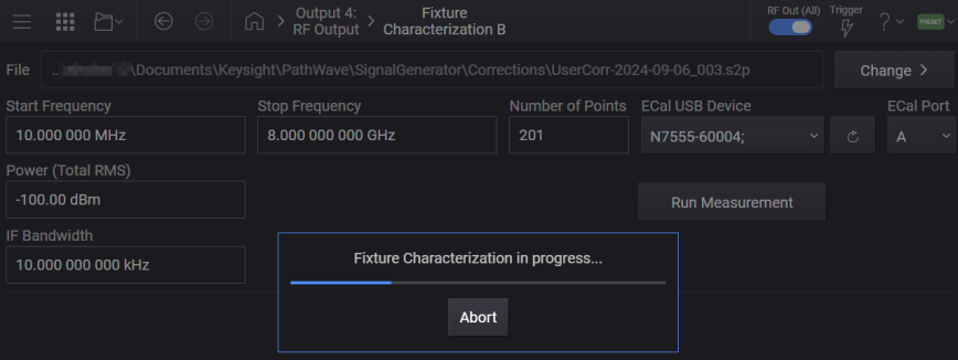
Upon successful completion of the measurement:
The resulting linear correction data is saved to the specified .s2p file. If no file is specified, a file name is automatically created. Note that when a file path is provided, it can be either full or relative. When a relative path is provided, it will be based from the Corrections folder. For information on the correction file location, see File Location and Default Folders.
In the Block properties, the resulting .s2p file is used as the Fixture Characterization Correction File.
'Enable' setting is set to ON for the applicable Fixture Block.
Additionally, you can also include user data in the resulting .s2p file’s header when specified via the Run Measurement SCPI command. This user data can be provided in conjunction with a file path in the form of string key-value pairs. See example below.
Example: "/filepath.s2p","key=String Key 1,value=String Value 1","key=String Key 2,value=String Value 2"
You can also send the SCPI command with the file path specified as an empty string (see example below). In this case, the file name is automatically generated for the .s2p file with the provided user data.
Example: "","key=String Key 1,value=String Value 1","key=String Key 2,value=String Value 2"
|
GUI Location |
RF Output > Corrections/De-embedding > Block B, C, or D > Block Properties > Characterize > Run Measurement |
|
SCPI Command |
[:SOURce][:RF<channel>]:CORRection: BLOCk2|3|4:FIXTure:CHARacterize:RUN <"file path">[,<userdata>] |
|
SCPI Example |
RF1:CORR:BLOC2:FIXT:CHAR:RUN RF1:CORR:BLOC2:FIXT:CHAR:RUN "file.s2p" RF1:CORR:BLOC2:FIXT:CHAR:RUN "file.s2p","key=FIXTURE serial,value=ABC123" |
|
Couplings |
When successful, sets Fixture Characterization Correction File to the resulting .s2p file and sets the correction block Enable to ON. |
| Notes |
For instruments with Option V08:
For instruments without Option V08:
|
|
State Saved |
No |
Aborts Fixture Characterization measurement.
|
GUI Location |
RF Output > Corrections/De-embedding > Block B, C, or D > Block Properties > Characterize > Run Measurement > Abort |
|
SCPI Command |
[:SOURce][:RF<channel>]:CORRection:BLOCk2|3|4:FIXTure:CHARacterize:ABORt |
|
SCPI Example |
RF1:CORR:BLOC2:FIXT:CHAR:ABOR |
|
State Saved |
No |
For the
Any time the DUT's match changes so as to affect the measurement performance, it is recommended to remeasure and apply the DUT Reflection Coefficient correction.
To apply DUT Reflection Coefficient correction
Select the DUT block displayed in the Corrections/De-embedding setup screen.
From the DUT Reflection Coefficient section,
either click File > to specify a predefined .s1p file to be used for correction.
or click the Add from Measurement button to configure and run the DUT Reflection Coefficient measurement to generate a .s1p file for correction.
Click the Enable checkbox to apply the correction stored in the .s1p file.
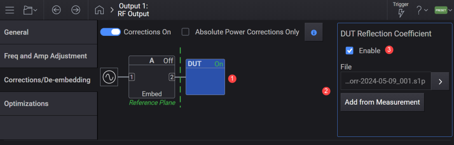
The specified .s1p file is applied when DUT Reflection Coefficient > Enable setting is ON.
|
SCPI Command |
[:SOURce][:RF<channel>]:CORRection:RCOefficient:FILE <file> [:SOURce][:RF<channel>]:CORRection:RCOefficient:FILE? |
|
SCPI Example |
RF1:CORR:RCO:FILE "corr.s1p" RF1:CORR:RCO:FILE? |
|
Preset |
None |
|
State Saved |
Yes |
Applies the DUT Reflection Coefficient Correction stored in the provided .s1p correction file.
|
SCPI Command |
[:SOURce][:RF<channel>]:CORRection:RCOefficient:ENABle ON|OFF|1|0 [:SOURce][:RF<channel>]:CORRection:RCOefficient:ENABle? |
|
SCPI Example |
RF1:CORR:RCO:ENAB ON RF1:CORR:RCO:ENAB? |
|
Notes |
For instruments without Option V08:
For instruments with Option V08:
|
|
Preset |
None |
|
State Saved |
Yes |
|
Range |
OFF|ON |
Only applies the absolute power, phase and time corrections to the. s1p data.
|
SCPI Command |
[:SOURce][:RF<channel>]:CORRection:CFConly2[:STATe] ON|OFF|0|1 [:SOURce][:RF<channel>]:CORRection:CFConly2[:STATe]? |
|
SCPI Example |
CORR:CFC2 ON CORR:CFC2? |
|
Preset |
0 |
|
State Saved |
Yes |
| Backwards Compatibility SCPI |
[:SOURce][:RF<channel>]:CORRection:APConly[:STATe] |
| Backwards Compatibility Notes |
Alias [:SOURce][:RF<channel>]:CORRection:APConly[:STATe] to [:SOURce][:RF<channel>]:CORRection:CFConly2[:STATe] See Also - Block > Center Frequency Corrections Only |
Query only. Reports the change in amplitude and phase flatness when DUT Reflection Coefficient > Enable setting is ON for the specified channel. For CW signals, this is a single value. For other signal types, this is an array of values versus frequency.
|
SCPI Command |
[:SOURce][:RF<channel>]:CORRection:RCOefficient:DATA? |
|
SCPI Example |
RF1:CORR:RCO:DATA? |
|
Notes |
For instruments with Option V08:
|
|
State Saved |
No |
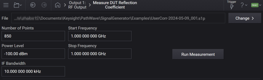
You can use the Add from Measurement button to access the Measure DUT Reflection Coefficient screen. Using this screen, you can configure and run the DUT Reflection Coefficient measurement. The linear correction data generated from this measurement is saved to a .s1p file. This file is then used as the DUT Reflection Coefficient correction file.
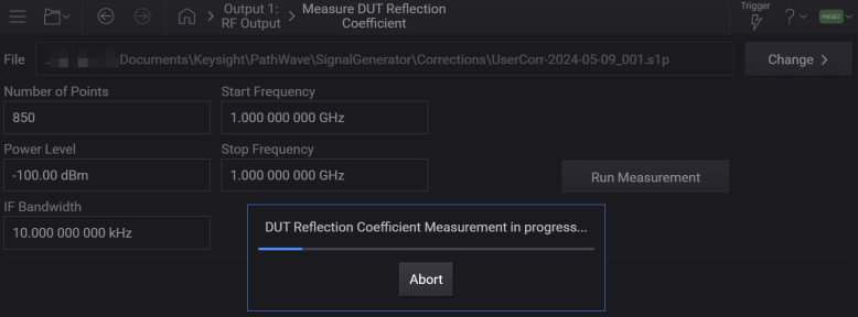
Runs the DUT Reflection Coefficient measurement.
Upon successful completion of this measurement:
The resulting linear correction data is saved to the specified .s1p file. If no file is specified, a file name is automatically created. Note that when a file path is provided, it can be either full or relative. When a relative path is provided, it will be based from the Corrections folder. For information on the correction file location, see File Location and Default Folders.
The resulting file is used to set the DUT Reflection Coefficient Correction File.
DUT Reflection Coefficient > Enable setting is set to ON.
Note that the measurement can be aborted by the Abort command.
Additionally, user data can be included in the resulting file’s header when specified via SCPI. This user data must be provided in conjunction with a file path in the form of string key-value pairs, see example 1. If an automatically generated filename is desired with user data provided, the command should be sent with the file path specified as an empty string, see example 2.
Example 1: "/filepath.s1p","key=String Key 1,value=String Value 1","key=String Key 2,value=String Value 2"
Example 2: "","key=String Key 1,value=String Value 1","key=String Key 2,value=String Value 2"
Reflection Coefficient can be measured on all single, dual, and quad channel configurations.
For information on Correction / De-embedding, see Corrections/De-embedding.
|
SCPI Command |
[:SOURce][:RF<channel>]:CORRection:RCOefficient:RUN <"file path">[,<userdata>] |
|
SCPI Example |
RF1:CORR:RCO:RUN RF1:CORR:RCO:RUN "file.s1p" RF1:CORR:RCO:RUN "file.s1p","key=DUT serial,value=ABC123" |
|
Couplings |
When successful, sets DUT Reflection Coefficient Correction File to the resulting .s1p file and sets Apply DUT Reflection Coefficient Correction to ON. |
|
Notes |
For instruments with Option V08: Attempting to run will raise the following errors/warnings depending on the conditions.
|
|
State Saved |
No |
Aborts DUT Reflection Coefficient measurement.
|
SCPI Command |
[:SOURce][:RF<channel>]:CORRection:RCOefficient:ABORt |
|
SCPI Example |
RF1:CORR:RCO:ABOR |
|
State Saved |
No |
Sets the start frequency for the DUT Reflection Coefficient Measurement correction point array.
|
SCPI Command |
[:SOURce][:RF<channel>]:CORRection:RCOefficient:STARt <freq> [:SOURce][:RF<channel>]:CORRection:RCOefficient:STARt? |
|
SCPI Example |
RF1:CORR:RCO:STAR 3GHz RF1:CORR:RCO:STAR? |
|
Couplings |
Coupled to Stop Frequency. |
|
Preset |
1 GHz |
|
State Saved |
Yes |
|
Min |
9 kHz |
|
Max |
With Option 503 = 3 GHz With Option 506 = 6 GHz With Option 508 = 8.5 GHz |
|
Resolution |
0.00001 Hz |
Sets the stop frequency for the DUT Reflection Coefficient Measurement correction point array.
|
SCPI Command |
[:SOURce][:RF<channel>]:CORRection:RCOefficient:STOP <freq> [:SOURce][:RF<channel>]:CORRection:RCOefficient:STOP? |
|
SCPI Example |
RF1:CORR:RCO:STOP 3GHz RF1:CORR:RCO:STOP? |
|
Couplings |
Coupled to Start Frequency. If Stop Frequency goes below Start Frequency, Start Frequency is automatically adjusted to Stop Frequency. |
|
Preset |
2 GHz |
|
State Saved |
Yes |
|
Min |
9 kHz |
|
Max |
With Option 503 = 3 GHz With Option 506 = 6 GHz With Option 508 = 8.5 GHz |
|
Resolution |
0.00001 Hz |
Defines the number of points in the DUT Reflection Coefficient Measurement correction step array. A frequency spacing of 10 MHz is optimal.
|
SCPI Command |
[:SOURce][:RF<channel>]:CORRection:RCOefficient:POINts <integer> [:SOURce][:RF<channel>]:CORRection:RCOefficient:POINts? |
|
SCPI Example |
RF1:CORR:RCO:POIN 1000 RF1:CORR:RCO:POIN? |
|
Preset |
850 |
|
State Saved |
Yes |
|
Min |
2 |
|
Max |
8500 |
Defines the IF bandwidth for the DUT Reflection Coefficient Measurement. Reducing the IF receiver bandwidth reduces the effect of random noise on a measurement. Each tenfold reduction in IF bandwidth lowers the noise floor by 10 dB.
|
SCPI Command |
[:SOURce][:RF<channel>]:CORRection:RCOefficient:BANDwidth <freq> [:SOURce][:RF<channel>]:CORRection:RCOefficient:BANDwidth? |
|
SCPI Example |
RF1:CORR:RCO:BAND 100 RF1:CORR:RCO:BAND? |
|
Preset |
1 kHz |
|
State Saved |
Yes |
|
Min |
1 Hz |
|
Max |
100 MHz |