9. Real-time Modulation Filter
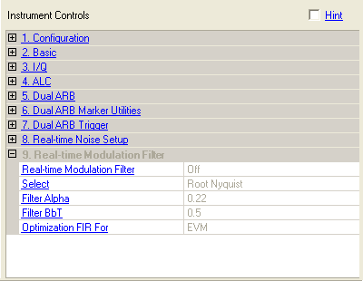
The following figure is a composite of all supported instruments, so some parameters may not apply to your instrument.

Real-Time Modulation Filter is available on firmware version A.01.50 or later for the N5182A, B.01.00 or later for the N5172B and N5182B, and C.05.24 or later for the E4438C. It is not available on E8267D. The filter works with only the carrier selection and only with a single carrier.
When the Real-Time Modulation Filter is turned on and the hardware connection is established, the Arb Mode Filter selection changes to None and the other filter settings gray out (the signal generator provides the filtering in real-time). Also the Oversampling Ratio selection is set to AUTO and becomes grayed out.
The cells within this function table provide only information, and they cannot be edited. When you turn the filter on, the software automatically selects the FIR filter type and configures its settings as shown in the above figure. To turn the filter on or off, use the Uplink Carrier view.
Unlike the other filter selections in this software, where the filtering is factored into the waveform file, the real-time modulation filter is a physical FPGA filter located on the signal generator. The purpose of this filter is to allow the storage of a large waveform file that if created using the software filters, may exceed the memory capacity of the signal generator.
When the filter is set to on, the software creates a waveform file without any filtering, which essentially equates to a waveform with an oversampling ratio (OSR) of one. This lack of filtering during waveform file creation produces a waveform that just contains the I/Q symbol decision points. This waveform creation process results in a waveform file size that is smaller by a factor of two or more. For example, an OSR of two would create a waveform file that is two times larger than a file using an OSR of one. When the signal generator plays the waveform file, the real-time modulation filter, in real-time, provides the correct filtering to produce the proper signal per the 3GPP specifications. The software stores the real-time modulation filter settings that include the FIR filter parameters in the waveform file header.
While the software does not provide any editing features for the real-time modulation filter, the signal generator does provide editing capability. The settings are located in the signal generator's menu. But if you do make filter changes and then download the waveform, the software changes the parameters back to the software's settings. For more information on the filter or the Dual ARB, refer to the Signal Generator User's Guide.
Real-time Modulation Filter
Displays whether the filter is on or off. Use the Uplink Carrier or Downlink Carrier view to turn the filter on or off.
Select
Shows the current FIR filter, which is always a Root Nyquist filter.
Filter Alpha
Displays the Root Nyquist filter alpha, which is always 0.22.
Filter BbT
Displays the BbT value. While the software shows this value, it is not used because the software always selects the Root Nyquist filter.
Optimization FIR For
Shows that the Root Nyquist filter is optimized for EVM (error vector magnitude).
The design of the Nyquist and Root Nyquist filters lend themselves to slight imperfections that allow for corrections to optimize the filters for either EVM with the most ideal pass band or ACPR with improved stop band rejection that does not change the bandwidth or alpha.