Carrier n - Downlink

| 3GPP | Baseband | Arb Mode Filter |
|---|---|---|
|
|
||
|
|
||
|
|
||
|
|
||
|
|
||
|
|
||
|
|
||
|
|
||
|
|
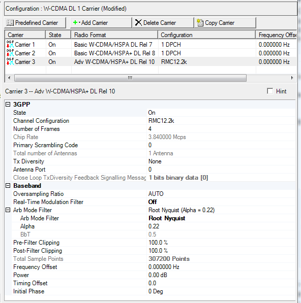
Carrier Configuration Summary Table
This table enables you to view the key parameters for each carrier in the waveform. You can also add or delete carriers using the buttons above the table (see descriptions below). Double-clicking a carrier row activates the setup tables for that carrier. You can use a maximum of 128 carriers.
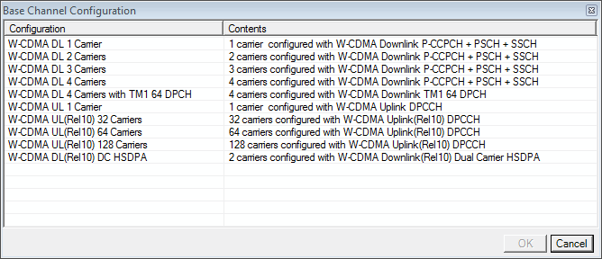
 This button opens a window of
  predefined carrier configuration selections.
Double-clicking a configuration replaces the current configuration in
the setup table.
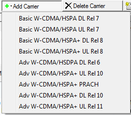
 This button opens a
  drop-down
menu
for selecting a carrier to add to the setup table. The carrier is inserted
above the currently highlighted carrier in the table.
 This button deletes the currently highlighted
carriers in the setup table. You can highlight multiple carriers by holding
down the CTRL key while selecting the carriers. You can also use the SHIFT
key to select a succession (group) of carriers.
 This button quickly adds a copy of the selected carrier in the carrier configuration summary table.
 An asterisk shown with a carrier entry indicates that
the parameters of a channel for that carrier have changed.
3GPP
State
Double-click or use the drop-down menu to control the operating state of the carrier.
Channel Configuration
Double-click or use the drop-down menu to change the channel configuration.
Waveform Generation Length
Choices: 1 slot (0.66...ms) | 2 slots (1.33...ms) | 3 slots ( 2.0 ms) | 4 slots (2.66...ms) | 5 slots (3.33...ms) | 6 slots (4.0 ms) | 7 slots (4.66...ms) | 8 slots (5.33...ms) | 9 slots (6.0 ms) | 10 slots (6.66...ms) | 11 slots (7.33... ms) | 12 slots 8.0 ms) | 13 slots (8.66...ms) | 14 slots (9.333...ms) | 1 frame (10 ms)
Default: 1 frames (10 ms)
Select the waveform generation length.
When the waveform generation length value is less than one frame (10 ms), set the Waveform Generation Offset value to create the waveform with the desired slot(s).
This parameter is available on only the Basic W-CDMA/HSPA DL/UL Rel 7 and Basic W-CDMA/HSPA+ DL/UL Rel 8 carriers.
Waveform Generation Offset
Range: 0–14
Default: 0
Sets the waveform generation offset. Enter an integer value by highlighting and replacing the current value. If just the number is highlighted and replaced, ensure that a space is present between the offset value and 'slot'. For example: 5 slot (3.33... ms), not 5slot (3.33... ms).
This parameter becomes active when the Waveform Generation Length setting is other than 1 frame (10 ms). The sum of the offset value and the Waveform Generation Length cannot be greater than 15 (15 slots in a radio frame). If the Waveform Generation Length is changed so that the sum would be greater than 15, the software changes the offset value so that the sum does not exceed 15.
This parameter is available on only the Basic W-CDMA/HSPA DL/UL Rel 7 and Basic W-CDMA/HSPA+ DL/UL Rel 8 carriers.
Number of Frames
Range: 4 to 4096
Default: 4
This setting requires the advanced Option Qxx and is available with only the carrier.
Enter the number of frames for the selected carrier.
The waveform length in a multi-carrier waveform is determined by the least common multiple (LCM) of the waveform lengths (measured in number of frames) of all the carriers. Carriers with waveform lengths less than the LCM are repeated until the multi-carrier waveform length matches the LCM. For example, if a waveform is comprised of two carriers, where carrier A is 10 frames and carrier B is 3 frames, A is repeated 3 times and B is repeated 10 times. This results in a multi-carrier waveform length of 30 frames, the LCM of carrier A and B.
The maximum waveform length depends on the oversampling ratio, number of carriers, and available PC memory. If an out-of-memory error is reported, reduce the number of frames, number of carriers, or the maximum frequency offset. Reducing the frequency offset reduces the oversampling ratio, which reduces the amount of PC memory required.
Chip Rate
View the W-CDMA signal chip rate (3.84 Mcps). You cannot edit this cell.
Primary Scrambling Code
Range: 0–511
Enter the primary scramble code. Entering a value here sets the scramble code for all downlink channels.
Total Number of Antenna
Range: 1 Antenna | 2 Antenna
Default: 1 Antenna
Specify the total number of antennas used for downlink transmission.
This parameter is read-only.
If you want to change this parameter, you need change the number of signal generators by selecting different Quick Setups. For example, in Quick Setups, RF Output (for Signal Generator) means 1 antenna; 2x2 MIMO Tx (for Signal Generator) means 2 antennas.
When you select 2x2 MIMO in Quick Setups, there are two instrument nodes under Hardware.
Tx Diversity
 drop-down menu to select
whether or not to use transmit diversity. When active, the software applies
STTD encoding, and for the SCH (PSCH
and SSCH), TSTD encoding. During
transit diversity operation, the software does not incorporate any DTX
periods.
drop-down menu to select
whether or not to use transmit diversity. When active, the software applies
STTD encoding, and for the SCH (PSCH
and SSCH), TSTD encoding. During
transit diversity operation, the software does not incorporate any DTX
periods.Antenna Port
Range: 0 | 1
Default: 0
In multi-antenna configurations, specify the antenna to be used for transmitting the downlink signal. The available selections are determined by the Total Number of Antennas setting.
Close Loop TxDiversity Feedback Signalling Message
Default: 0
Edit the Feedback Signaling Message (FSM) for Close Loop TxDiversity. This is only valid when TxDiversity is , or .
Baseband
Oversampling Ratio
Range: 0–50 | Auto
Default: Auto
Double-click or use the pull-down menu to set the oversampling ratio.
The Waveform Generation Length value (number of points) is automatically determined based on the oversampling ratio. Using a larger oversampling ratio results in a more completely filtered image, but also uses more waveform memory by increasing the number of waveform points. Choose to let the signal generator automatically select the optimized oversample ratio for the current signal setup.
This parameter is coupled with Frequency Offset. Use the following formula to calculate the minimum oversampling ratio:
minimum oversampling ratio = (3.84 MHz + 2(2.5 MHz + Frequency Offset))/3.84 MHz
Round all decimal values to the next higher oversampling number. For example, if the calculated value is 12.1, select 13 as the minimum oversampling ratio value.
The oversampling ratio must be set to any value other than 1 in order to select a filter type. An oversampling ratio of 1 automatically selects as the filter type and makes associated filter parameters unavailable.
Real-Time Modulation Filter
Choices: Off | On
Default: On
The E4438C ESG, N5182A MXG, N5172B EXG, and N5182B MXG signal generators are the only instruments that support the Real-Time Modulation Filter. For this software, it supports this feature with Option Qxx and its , , and carriers.
When set to On, the software creates a waveform with an oversampling ratio of one and without any filtering. When played back, the signal generator uses the real-time modulation filter to increase the oversampling ratio and to provide the correct filtering. For more information and to view the signal generator filter settings, refer to the topic.
The purpose of this filter is to allow the signal generator storage of a large waveform file that, if created using the software filters, may exceed the memory capacity of the signal generator. This feature is especially useful for creating a waveform to transmit a full PN9 sequence for BER testing.
When turned on, the selection changes to and the other filter settings gray out (the signal generator provides the filtering in real-time). Also the selection sets to and it cannot be changed.
ARB Mode Filter
View the selected filter type and associated parameter.
ARB Mode Filter
Double-click or use the pull-down menu to set the baseband filter type:
-
None
-
Nyquist
-
Root Nyquist
-
Rectangle
-
Gaussian
If the oversampling ratio is set to 1, the filter type is automatically set to None, and the filter types and corresponding filter parameters are not available.
If the oversampling ratio is set to any other value, you can select one of the listed filter types and edit the associated parameters.
Alpha
Change the Alpha parameter for Root Nyquist and Nyquist filters. This field grays out with any other filter selection.
BbT
Change the BbT parameter for a Gaussian filter. This field grays out with any other filter selection.
Pre-Filter Clipping
Range: 10–100%
Default: 100%
Set the clip (limit) level of the I/Q waveform before filtering. A level of 100.0% equates to no clipping.
Post-Filter Clipping
Range: 10–100%
Default: 100%
Set the clip (limit) level of the I/Q waveform after filtering. A level of 100.0% equates to no clipping.
Total Sample Points
View the Waveform Length, displayed in points. You cannot edit this cell.
Waveform Length is directly related to the Oversampling Ratio value selected. The higher the Oversampling Ratio, the larger the waveform:
|
Oversampling Ratio |
Waveform Length |
|---|---|
|
1 |
38400 |
|
2 |
76800 |
|
|
|
|
50 |
1920000 |
Frequency Offset
Range:
N5182B : –76.5 to 76.5 MHz (Option 657)
N5172B : –56.5 to 56.5 MHz (Option 655)
N5182A: –49.5 to 49.5 MHz
E4438C: –39.5 to 39.5 MHz
E8267D: –39.5 to 39.5 MHz
N5106A: –49.5 to 49.5 MHz
E6607: –49.5 to 49.5 MHz
Default:
0 Hz
Set the frequency offset for the carrier relative to the signal generator's frequency setting.
This parameter is coupled with Oversampling Ratio.
Power
Range: –65 to 0 dB
Default: 0 dB
Use this cell to set the relative power level for the selected carrier in a multiple carrier configuration. To set the power level for a single carrier configuration, use the cell in the Instrument view.
In a multiple carrier configuration, each carrier's power level is set relative to the signal generator's RF power level. The signal generator distributes the RF power among the carriers while maintaining their power ratios. For example with two carriers set to 0 dB, each carrier is at the same power level but both carriers are -3 dB down from the reference. As you increase the number of carriers, the power level decreases the same amount for each carrier.
Timing Offset
Range: 0–149, in 0.5 steps
Default: 0
Set the timing offset of the carrier.
Timing offset values increment by 256 chips for each half (0.5) step and by 512 chips for each whole step.
Physical channels summed in phase produce a high crest factor (high peak-to-average ratio). Offsetting the timing can minimize the crest factor.
Initial Phase
Range: 0–359 degrees
Default: 0 degrees
Set the initial phase of the carrier.
Calculating Downlink Scramble Codes


