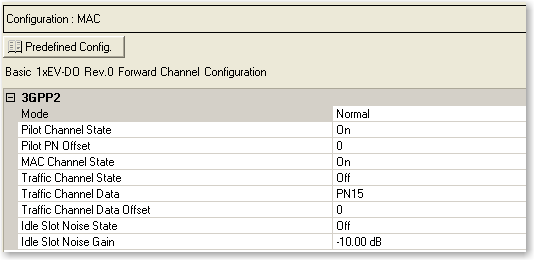
Channel Setup: Basic 1xEV-DO Rev.0 Forward
|
|
Buttons
Opens a  drop-down menu
of predefined channel configuration selections. Double-clicking a configuration
replaces the current configuration in the Channel Configuration window
and displays it at the top of the window.
drop-down menu
of predefined channel configuration selections. Double-clicking a configuration
replaces the current configuration in the Channel Configuration window
and displays it at the top of the window.
3GPP2
Mode
Selections: Normal, Continuous Pilot
Default: Normal
Sets the operating mode.
Normal - In this mode, a 1xEV-DO frame with custom channel configurations in each of the frame's 16 timeslots can be configured. The pilot channel, MAC channel, and traffic channel are supported in normal operating mode.
Continuous Pilot - This mode provides a fundamental test signal to be used as a troubleshooting tool to verify basic operation of the device under test. Instead of two pilot channel bursts occurring in each of the frame’s 16 timeslots, the pilot channel is continuously active during each frame timeslot, and thus over the entire 1xEV-DO frame. In this mode of operation, the pilot channel is the only available channel type.
Pilot Channel State
Selections: On, Off
Default: On
Is the default active channel in every frame and occurs as two distinct bursts (in normal mode) in each timeslot of the frame.
Pilot PN Offset
Range: 0 to 511
Default: 0
Sets the pilot channel’s PN offset index. The PN offset of the pilot channel indicates the cell or sector of the transmitting access network.
MAC Channel State
Selections: On, Off
Default: On
Sets the state of the medium access control (MAC) channel for the entire frame. Any channel configuration done at the timeslot level is not valid unless the channel is activated for use in the entire frame.
Traffic Channel State
Selections: On, Off
Default: Off
Sets the state of the traffic channel for the entire frame. Any channel configuration done at the timeslot level is not valid unless the channel is activated for use in the entire frame.
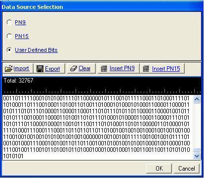
Traffic Channel Data
Selections: PN15
Default: PN9, PN15, User Defined Bits
Sets the data type (bit pattern) for the traffic channel. The traffic channel must be activated before you can select the data type.
The traffic channel bit stream is divided into each timeslot with an active traffic channel for the entire frame. In the case of PN sequences, a continuous PN sequence is distributed across the timeslots with an active traffic channel. After the last timeslot with an active traffic channel has been filled with data, the PN sequence is truncated.
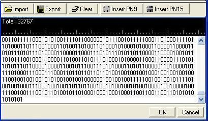
The  icon at the right of the entry box opens
the Data Source Selection dialog box.
icon at the right of the entry box opens
the Data Source Selection dialog box.
Traffic Channel Data Offset
Range: 0 to 32768
Default: 0
Sets the number of bits that the payload data is offset. For example, if the payload data is 0110 and the offset is 2, the resulting bit stream begins with the third bit (1), skipping over the first two (01) before continuing to repeat the selected pattern (0110). Therefore, in this example, the pattern would be 10011001100110... and so on.
Idle Slot Noise State
Selections: On, Off
Default: Off
Allows an idle slot to have a controllable low level of noise, rather than no signal, to improve the on/off ratio that must be handled by the component. This low level of the noise is controlled by the Idle Slot Gain parameter. During idle slot transmission, a large on/off power ratio requires that the access network power amplifier have extremely wide dynamic range. This is typically not the case. To address this issue, the idle slot noise function allows the noise level during the off time of the idle slot to be varied relative to the pilot channel. By varying the idle slot gain, the on/off power ratio can be set as needed to meet the transmission envelope mask requirements of the system. When the idle slot noise is disabled, RF blanking (turning off the RF signal in certain conditions) is automatically enabled, which results in a very large on/off power ratio during idle slot transmission.
Idle Slot Noise Gain
Range: -80 dB to 0 dB
Default: -10 dB
Allows the noise level during the off time of the idle slot to be varied relative to the pilot channel. By varying the idle slot gain, the on/off power ratio can be set as needed to meet the transmission envelope mask requirements of the system. To set the idle slot gain, the idle slot noise function must be enabled first.