Selections: None | Marker 1-4
Default: None
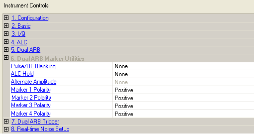
Selects an RF blanking function. Use this cell after downloading and synchronizing with the signal generator.
None − disables RF blanking.
Marker 1 through 4 − selects a marker to activate RF blanking. This turns off the RF output signal during specific conditions determined by the marker. Do not blank longer than 100 ms due to ALC hold limit.
Selections: None | Marker 1-4
Default: None
Selects a marker for ALC Hold. Use ALC Hold when you have a waveform signal that has idle periods, or when the increased dynamic range with RF blanking is not desired. Use this cell after downloading and synchronizing with the signal generator.
None − disables ALC hold.
Marker 1 through 4 − assigns a marker for the ALC hold function. When the specified marker polarity is positive and the marker signal is low (no marker points), ALC hold is on, and output power leveling does not respond to changes to the signal amplitude. When the marker signal is high, the ALC samples the waveform points and averages the waveform amplitudes to set the ALC circuitry for the next ALC hold period. Limit ALC Hold to no more than 100 ms, as the ALC Level may degrade.
Choice: None | Marker 1 to 4
Default: None
This parameter is not available for the N5182A signal generator and is grayed out.
Use this cell after downloading and synchronizing with the signal generator.
Double-click or use the drop-down menu to select a marker for enabling the alternate amplitude function.
None − disables the alternate amplitude function.
Marker 1 through 4 − assigns a marker for the alternate amplitude function. When the specified marker polarity is positive and the marker signal is low (no marker points), alternate amplitude is off. When the marker signal is high, the alternate amplitude function is on.
Configure the alternate amplitude parameters from the Amplitude hardkey menu of the signal generator.
For more information about alternate amplitude and marker settings, refer to the signal generator's User's Guide.
Selections: Positive, Negative
Default: Positive
Selects the active polarity for Marker 1-4. Use this cell after downloading and synchronizing with the signal generator.
Positive − the marker signal is high during the marker points.
Negative − the marker signal is high during the period of no marker points.
When Parameter Optimization in the Signal Generator node is set to , Marker 3 and Marker 4 source selection in the Waveform Setup node and the marker routing selected in the Dual Arb Marker Utilities are overridden.
To manually set Marker 3 and Marker 4 source, the marker routing, or both, set the Parameter Optimization to .