Real Time
WFM "N"
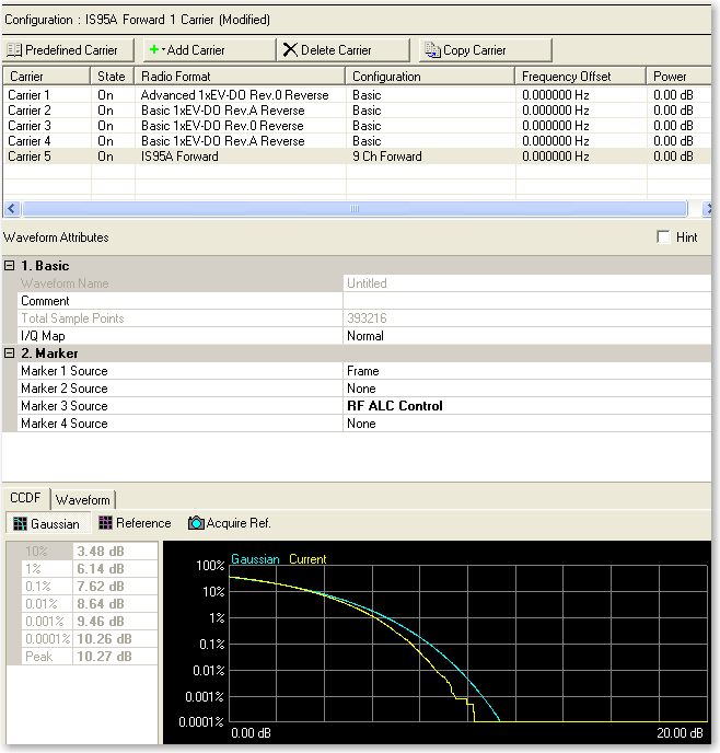
Carrier Configuration Summary Table
This table enables you to view the key parameters for each carrier in
the waveform. You can also add or delete carriers using the buttons above
the table (see descriptions below). Double-clicking a carrier row activates
the setup tables for that carrier.

Opens a  drop-down menu
of predefined carrier configuration selections. Double-clicking a configuration
replaces the current configuration in the Carrier Configuration Summary
Table.
drop-down menu
of predefined carrier configuration selections. Double-clicking a configuration
replaces the current configuration in the Carrier Configuration Summary
Table.

Opens a drop-down menu
which allows you to add a carrier to the current configuration.
The new carrier is added immediately above the currently highlighted
carrier in the Carrier Configuration Summary Table.

Deletes the currently highlighted carrier in the Carrier Configuration
Summary Table. You can highlight multiple carriers by holding down the
CTRL key while selecting the carriers. You can also use the SHIFT key
to select a succession (group) of carriers.

Copies the highlighted carrier and appends it at the bottom of the carrier
list.
Waveform Attributes
1. Basic
Waveform Name
Displays the name of the waveform entered in the waveform setup window. It cannot be edited in
this cell.
Comment
Allows you to enter an alpha-numeric comment up to 32 characters in
length. The comment may be unique for each individual waveform.
Total Sample
Points
Displays the number of sample points. This field is updated after the
waveform is generated and cannot be edited.
I/Q Map
Selections: Normal, Invert
Default: Normal
Allows you to select a normal or inverted I/Q signal. The  icon at the right edge of the entry box displays
a drop-down list with all available selections.
icon at the right edge of the entry box displays
a drop-down list with all available selections.
2. Marker
Marker 1 Source
Selections: None, Frame, RF ALC Control,
RF Blanking Control, Timing Control, User Defined Bits
Default: Frame
Defines the source of the marker points for Marker 1. Click  at the right edge of the cell to display the Marker Source
Selection dialog box
from which you can select the marker source.
at the right edge of the cell to display the Marker Source
Selection dialog box
from which you can select the marker source.
Select one of the following sources for the marker.
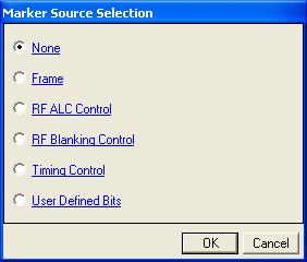
None
Sets all maker points are
set to zero (inactive).
Frame
Sets the first five marker bits of the frame to 1, which sets an active
marker for the first five waveform samples (waveform points). The signal
generator outputs the Marker 1 output from the rear-panel Event 1 output.
RF ALC Control
Activates the automatic leveling control (ALC) function. When enabled,
the ALC constantly monitors and controls the RF output power of the signal
generator.
The ALC circuit cannot properly handle some modulation conditions, leading
to output power level errors. In these conditions, turning the ALC off
and using the signal generator power search function can achieve better
power level accuracy.
RF Blanking
Control
Assigns a specific marker to activate RF blanking. The automatic leveling
control (ALC) hold is automatically enabled during output blanking.
RF Blanking Control improves the signal quality when the MAC channel
and/or traffic channel are de-activated in a timeslot. It does so by increasing
the on/off ratio of the forward link RF bursts.
When RF Blanking Control is enabled, the marker polarity must be set
to positive or the wanted RF signal will be blanked, resulting in no RF
output from the signal generator.
Timing Control
Sets the marker so that it is generated by the waveform.
IS95/cdma2000 generates the first five waveform samples (waveform points)
in the cycle. 1xEV-DO generates the half-slot timing.
User Defined
Bits
Opens the user data entry area,
which lets you customize the marker signal.
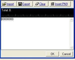
The data entry area contains
buttons to import, export, or clear user marker data along with the ability
to insert a PN9 sequence as the marker bits. Optionally you can manually
insert or delete marker data. To manually insert marker data, simply place
the cursor within the data entry area or highlight existing bits, and
insert bits. There are three ways to insert marker data:
-
using
the 1 (marker active) and 0 (marker inactive) keys on the keyboard
-
using
the Insert PN9 button
-
pasting data from a file
or from within the current view
(The key board shortcuts
Ctrl+C and Ctrl+V work for user data entry.)
To delete data, simply
place the cursor at the desired location within the data or highlight
bits, and delete data. The key board short cut Ctrl+Z also deletes highlighted
data.
The maximum number of marker
bits for the user data entry area is 2,097,152 which equals 32,768 (1short
code data points) * 64 (oversampling ratio). This is also the maximum
file size.
The four buttons in the
expanded area are:
Import
Loads a user-defined pattern from a selected
location. When you select this button, the Open user defined data dialog
box appears for navigating to and selecting the desired file. An imported
file automatically updates the user data entry area. The software accepts
the following file types:
The maximum file size is 2,097,152 bits. If the imported file is larger
than bits, the software truncates the bits to conform
to the maximum file size.
Export
Saves the current data pattern, showing
in the user data entry area, to a file. When you select this button, a
Save user defined data dialog box appears for navigating to the location
where you can save the file. The software saves the user data as one of
the following selected file types:
Clear
Clears all data showing in the user data entry area.
Insert PN9
Inserts a fixed pattern pseudo-random bit sequence containing 511 bits
(29–1) into the user data entry
area. The software generates this fixed pattern in accordance with the
CCITT recommendation O.153. Repeated clicking of this button adds additional
PN9 sequences until the software attains the maximum file size of 2,097,152
bits. The software truncates data in excess of the maximum file size.
To edit the data pattern, insert the cursor at the desired point in
the file and click Insert PN9, or enter the information manually using
the keyboard keys 1 and 0. The software inserts the data at the cursor
position and truncates all data in excess of 2,097,152 bits.
The software lets you create a file larger than it uses for the waveform.
When this occurs, the software truncates the excess marker bits. Conversely,
if there are not enough marker bits, the software repeats the marker bit
pattern until there are enough marker bits to match the Waveform Length
cell value.
The signal generator outputs the marker 1 signal from the rear-panel
EVENT 1 output. For more information, see the signal generator's User
Guide.
Marker 2 Source
Selections: None, Frame, RF ALC Control,
RF Blanking Control, Timing Control, User Defined Bits
Default: None
Defines the source of the marker points for Marker 2. Click
at the right edge of the cell to display the Marker Source
Selection dialog box
from which you can select the marker source.
Select one of the following sources for the marker.
None
Sets all maker points are
set to zero (inactive).
Frame
Sets the first five marker bits of the frame to 1, which sets an active
marker for the first five waveform samples (waveform points). The signal
generator outputs the Marker 1 output from the rear-panel Event 1 output.
RF ALC Control
Activates the automatic leveling control (ALC) function. When enabled,
the ALC constantly monitors and controls the RF output power of the signal
generator.
The ALC circuit cannot properly handle some modulation conditions, leading
to output power level errors. In these conditions, turning the ALC off
and using the signal generator power search function can achieve better
power level accuracy.
RF Blanking
Control
Assigns a specific marker to activate RF blanking. The automatic leveling
control (ALC) hold is automatically enabled during output blanking.
RF Blanking Control improves the signal quality when the MAC channel
and/or traffic channel are de-activated in a timeslot. It does so by increasing
the on/off ratio of the forward link RF bursts.
When RF Blanking Control is enabled, the marker polarity must be set
to positive or the wanted RF signal will be blanked, resulting in no RF
output from the signal generator.
Timing Control
Sets the marker so that it is generated by the waveform.
IS95/cdma2000 generates the first five waveform samples (waveform points)
in the cycle. 1xEV-DO generates the half-slot timing.
User Defined
Bits
Opens the user data entry area,
which lets you customize the marker signal.
The data entry area contains
buttons to import, export, or clear user marker data along with the ability
to insert a PN9 sequence as the marker bits. Optionally you can manually
insert or delete marker data. To manually insert marker data, simply place
the cursor within the data entry area or highlight existing bits, and
insert bits. There are three ways to insert marker data:
-
using
the 1 (marker active) and 0 (marker inactive) keys on the keyboard
-
using
the Insert PN9 button
-
pasting data from a file
or from within the current view
(The key board shortcuts
Ctrl+C and Ctrl+V work for user data entry.)
To delete data, simply
place the cursor at the desired location within the data or highlight
bits, and delete data. The key board short cut Ctrl+Z also deletes highlighted
data.
The maximum number of marker
bits for the user data entry area is 2,097,152 which equals 32,768 (1short
code data points) * 64 (oversampling ratio). This is also the maximum
file size.
The four buttons in the
expanded area are:
Import
Loads a user-defined pattern from a selected
location. When you select this button, the Open user defined data dialog
box appears for navigating to and selecting the desired file. An imported
file automatically updates the user data entry area. The software accepts
the following file types:
The maximum file size is 2,097,152 bits. If the imported file is larger
than bits, the software truncates the bits to conform
to the maximum file size.
Export
Saves the current data pattern, showing
in the user data entry area, to a file. When you select this button, a
Save user defined data dialog box appears for navigating to the location
where you can save the file. The software saves the user data as one of
the following selected file types:
Clear
Clears all data showing in the user data entry area.
Insert PN9
Inserts a fixed pattern pseudo-random bit sequence containing 511 bits
(29–1) into the user data entry
area. The software generates this fixed pattern in accordance with the
CCITT recommendation O.153. Repeated clicking of this button adds additional
PN9 sequences until the software attains the maximum file size of 2,097,152
bits. The software truncates data in excess of the maximum file size.
To edit the data pattern, insert the cursor at the desired point in
the file and click Insert PN9, or enter the information manually using
the keyboard keys 1 and 0. The software inserts the data at the cursor
position and truncates all data in excess of 2,097,152 bits.
The software lets you create a file larger than it uses for the waveform.
When this occurs, the software truncates the excess marker bits. Conversely,
if there are not enough marker bits, the software repeats the marker bit
pattern until there are enough marker bits to match the Waveform Length
cell value.
The signal generator outputs the marker 2 signal from the rear-panel
EVENT 2 output. For more information, see the signal generator's User
Guide.
Marker 3 Source
Selections: None, Frame, RF ALC Control,
RF Blanking Control, Timing Control, User Defined Bits
Default: None
Defines the source of the marker points for Marker 3. Click
at the right edge of the cell to display the Marker Source
Selection dialog box
from which you can select the marker source.
The signal generator outputs the marker 3 signal from the rear-panel
EVENT 3 output. For more information, see the signal generator's User
Guide.
When Parameter
Optimization in the Signal Generator node is set to ,
Marker 3 and Marker 4 source selection in the Waveform Setup node and
the marker routing selected in the Dual Arb Marker Utilities are overridden.
To manually set Marker 3 and Marker 4 source, the marker routing, or
both, set the Parameter Optimization to .
Select one of the following sources for the marker.
None
Sets all maker points are
set to zero (inactive).
Frame
Sets the first five marker bits of the frame to 1, which sets an active
marker for the first five waveform samples (waveform points). The signal
generator outputs the Marker 1 output from the rear-panel Event 1 output.
RF ALC Control
Activates the automatic leveling control (ALC) function. When enabled,
the ALC constantly monitors and controls the RF output power of the signal
generator.
The ALC circuit cannot properly handle some modulation conditions, leading
to output power level errors. In these conditions, turning the ALC off
and using the signal generator power search function can achieve better
power level accuracy.
RF Blanking
Control
Assigns a specific marker to activate RF blanking. The automatic leveling
control (ALC) hold is automatically enabled during output blanking.
RF Blanking Control improves the signal quality when the MAC channel
and/or traffic channel are de-activated in a timeslot. It does so by increasing
the on/off ratio of the forward link RF bursts.
When RF Blanking Control is enabled, the marker polarity must be set
to positive or the wanted RF signal will be blanked, resulting in no RF
output from the signal generator.
Timing Control
Sets the marker so that it is generated by the waveform.
IS95/cdma2000 generates the first five waveform samples (waveform points)
in the cycle. 1xEV-DO generates the half-slot timing.
User Defined
Bits
Opens the user data entry area,
which lets you customize the marker signal.
The data entry area contains
buttons to import, export, or clear user marker data along with the ability
to insert a PN9 sequence as the marker bits. Optionally you can manually
insert or delete marker data. To manually insert marker data, simply place
the cursor within the data entry area or highlight existing bits, and
insert bits. There are three ways to insert marker data:
-
using
the 1 (marker active) and 0 (marker inactive) keys on the keyboard
-
using
the Insert PN9 button
-
pasting data from a file
or from within the current view
(The key board shortcuts
Ctrl+C and Ctrl+V work for user data entry.)
To delete data, simply
place the cursor at the desired location within the data or highlight
bits, and delete data. The key board short cut Ctrl+Z also deletes highlighted
data.
The maximum number of marker
bits for the user data entry area is 2,097,152 which equals 32,768 (1short
code data points) * 64 (oversampling ratio). This is also the maximum
file size.
The four buttons in the
expanded area are:
Import
Loads a user-defined pattern from a selected
location. When you select this button, the Open user defined data dialog
box appears for navigating to and selecting the desired file. An imported
file automatically updates the user data entry area. The software accepts
the following file types:
The maximum file size is 2,097,152 bits. If the imported file is larger
than bits, the software truncates the bits to conform
to the maximum file size.
Export
Saves the current data pattern, showing
in the user data entry area, to a file. When you select this button, a
Save user defined data dialog box appears for navigating to the location
where you can save the file. The software saves the user data as one of
the following selected file types:
Clear
Clears all data showing in the user data entry area.
Insert PN9
Inserts a fixed pattern pseudo-random bit sequence containing 511 bits
(29–1) into the user data entry
area. The software generates this fixed pattern in accordance with the
CCITT recommendation O.153. Repeated clicking of this button adds additional
PN9 sequences until the software attains the maximum file size of 2,097,152
bits. The software truncates data in excess of the maximum file size.
To edit the data pattern, insert the cursor at the desired point in
the file and click Insert PN9, or enter the information manually using
the keyboard keys 1 and 0. The software inserts the data at the cursor
position and truncates all data in excess of 2,097,152 bits.
The software lets you create a file larger than it uses for the waveform.
When this occurs, the software truncates the excess marker bits. Conversely,
if there are not enough marker bits, the software repeats the marker bit
pattern until there are enough marker bits to match the Waveform Length
cell value.
Marker 4 Source
Selections: None, Frame, RF ALC Control,
RF Blanking Control, Timing Control, User Defined Bits
Default: None
Defines the source of the marker points for Marker 4. Click
at the right edge of the cell to display the Marker Source
Selection dialog box
from which you can select the marker source.
The signal generator outputs the marker 4 signal from the rear-panel
EVENT 4 output. For more information, see the signal generator's User
Guide.
When Parameter
Optimization in the Signal Generator node is set to ,
Marker 3 and Marker 4 source selection in the Waveform Setup node and
the marker routing selected in the Dual Arb Marker Utilities are overridden.
To manually set Marker 3 and Marker 4 source, the marker routing, or
both, set the Parameter Optimization to .
Select one of the following sources for the marker.
None
Sets all maker points are
set to zero (inactive).
Frame
Sets the first five marker bits of the frame to 1, which sets an active
marker for the first five waveform samples (waveform points). The signal
generator outputs the Marker 1 output from the rear-panel Event 1 output.
RF ALC Control
Activates the automatic leveling control (ALC) function. When enabled,
the ALC constantly monitors and controls the RF output power of the signal
generator.
The ALC circuit cannot properly handle some modulation conditions, leading
to output power level errors. In these conditions, turning the ALC off
and using the signal generator power search function can achieve better
power level accuracy.
RF Blanking
Control
Assigns a specific marker to activate RF blanking. The automatic leveling
control (ALC) hold is automatically enabled during output blanking.
RF Blanking Control improves the signal quality when the MAC channel
and/or traffic channel are de-activated in a timeslot. It does so by increasing
the on/off ratio of the forward link RF bursts.
When RF Blanking Control is enabled, the marker polarity must be set
to positive or the wanted RF signal will be blanked, resulting in no RF
output from the signal generator.
Timing Control
Sets the marker so that it is generated by the waveform.
IS95/cdma2000 generates the first five waveform samples (waveform points)
in the cycle. 1xEV-DO generates the half-slot timing.
User Defined
Bits
Opens the user data entry area,
which lets you customize the marker signal.
The data entry area contains
buttons to import, export, or clear user marker data along with the ability
to insert a PN9 sequence as the marker bits. Optionally you can manually
insert or delete marker data. To manually insert marker data, simply place
the cursor within the data entry area or highlight existing bits, and
insert bits. There are three ways to insert marker data:
-
using
the 1 (marker active) and 0 (marker inactive) keys on the keyboard
-
using
the Insert PN9 button
-
pasting data from a file
or from within the current view
(The key board shortcuts
Ctrl+C and Ctrl+V work for user data entry.)
To delete data, simply
place the cursor at the desired location within the data or highlight
bits, and delete data. The key board short cut Ctrl+Z also deletes highlighted
data.
The maximum number of marker
bits for the user data entry area is 2,097,152 which equals 32,768 (1short
code data points) * 64 (oversampling ratio). This is also the maximum
file size.
The four buttons in the
expanded area are:
Import
Loads a user-defined pattern from a selected
location. When you select this button, the Open user defined data dialog
box appears for navigating to and selecting the desired file. An imported
file automatically updates the user data entry area. The software accepts
the following file types:
The maximum file size is 2,097,152 bits. If the imported file is larger
than bits, the software truncates the bits to conform
to the maximum file size.
Export
Saves the current data pattern, showing
in the user data entry area, to a file. When you select this button, a
Save user defined data dialog box appears for navigating to the location
where you can save the file. The software saves the user data as one of
the following selected file types:
Clear
Clears all data showing in the user data entry area.
Insert PN9
Inserts a fixed pattern pseudo-random bit sequence containing 511 bits
(29–1) into the user data entry
area. The software generates this fixed pattern in accordance with the
CCITT recommendation O.153. Repeated clicking of this button adds additional
PN9 sequences until the software attains the maximum file size of 2,097,152
bits. The software truncates data in excess of the maximum file size.
To edit the data pattern, insert the cursor at the desired point in
the file and click Insert PN9, or enter the information manually using
the keyboard keys 1 and 0. The software inserts the data at the cursor
position and truncates all data in excess of 2,097,152 bits.
The software lets you create a file larger than it uses for the waveform.
When this occurs, the software truncates the excess marker bits. Conversely,
if there are not enough marker bits, the software repeats the marker bit
pattern until there are enough marker bits to match the Waveform Length
cell value.
Graphs
CCDF
Displays the Complimentary Cumulative Distribution Function (CCDF) graph.
This graph
shows the plot and peak-to-average values for the current waveform. A
waveform can only be plotted after it has been generated.
The CCDF graph displays the probability (in percentage) of the generated
carrier's calculated peak-to-average power ratio (measured in dB) meeting
or exceeding a certain level. The table to the left of the CCDF plot displays
the calculated peak-to-average values for the carrier. For additional
information, see Understanding
CCDF Curves.
Click  or
or  from the main tool
bar to generate an I/Q waveform and plot the CCDF graph using the
current channel configuration. Any changes to the channel configuration
setup do not appear on the graph until you generate the waveform. The
status bar at the bottom
of the screen shows waveform generation progress.
from the main tool
bar to generate an I/Q waveform and plot the CCDF graph using the
current channel configuration. Any changes to the channel configuration
setup do not appear on the graph until you generate the waveform. The
status bar at the bottom
of the screen shows waveform generation progress.
Each time you adjust parameters and generate a waveform, a plot is added
to the graph.
The graph retains your three most recent plots (in shades of gray), allowing
you to make comparisons of waveform characteristics.
Use the buttons shown below to plot the Gaussian data, reference data
and generated waveform data to the CCDF graph. The graph's initial state
shows only the Gaussian curve (blue) until you generate a waveform.
Gaussian
Toggles the view of the band-limited Gaussian noise curve (blue).
Reference
Toggles the view of the reference curve (red). The reference appears
as a flat line until you generate a waveform and click the button.
Acquire
Ref.
Sets the current waveform curve to yellow and the reference curve to
red. Click the button
to view the reference curve.
Waveform
Power
Selects different waveform plots. Selections include Power, I+Q,
I|Q,
and Spectrum.
Each click selects the next plot type in the list. You can also click
the arrow to access a drop-down menu where you can make a direct selection.
plots the I and Q curves overlapped.
Spectrum displays a frequency domain based plotting.
Related Topics
Waveform
Setup
Carrier
"N"