|
3GPP2 |
Baseband |
Signal Generator |
|
Tools |
||
|
Playback |
||
|
|
||
|
|
||
|
|
|
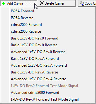
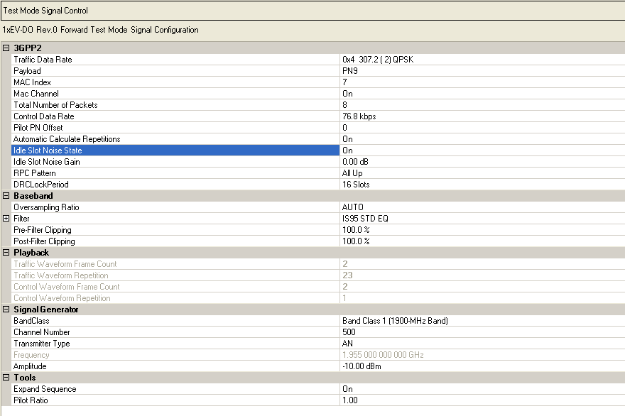
When 1xEV-DO Rev 0 Forward Test Mode Signal is enabled in  Waveform
Setup,
the Test Mode Signal Control node is added to the tree view. This is a special mode
for testing mobile handsets and cannot be used in a multicarrier waveform
setup. All Channel parameters are set in this Test Mode Signal Control pane and are
read-only parameters in the Traffic and Control Channel panes.
Waveform
Setup,
the Test Mode Signal Control node is added to the tree view. This is a special mode
for testing mobile handsets and cannot be used in a multicarrier waveform
setup. All Channel parameters are set in this Test Mode Signal Control pane and are
read-only parameters in the Traffic and Control Channel panes.
You can, however, add a fully coded 1xEV-DO Rev. 0 Forward Test Mode Signal channel
to a multicarrier setup by using the Add Channel
feature in either the Waveform Setup or Carrier Setup panes. When adding
1xEV-DO Rev. 0 Forward Test Mode Signal in a multicarrier setup, both traffic and control
channels are configurable.
Selections: Several selections available
from the drop-down
list
Default: 0x4 307.2 ( 2) QPSK
Sets the traffic channel data rate set. The ![]() icon at the right
edge of the entry box displays a drop-down list with all available selections.
Each traffic channel data rate set includes the data rate control (DRC)
value, data rate, number of slots per packet, and modulation type.
icon at the right
edge of the entry box displays a drop-down list with all available selections.
Each traffic channel data rate set includes the data rate control (DRC)
value, data rate, number of slots per packet, and modulation type.
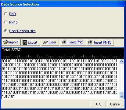
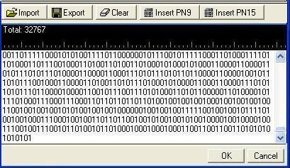
Selections: PN9, PN15, User Defined Bits
Default: PN9
Sets the data type (bit pattern) to be transmitted during the medium access control (MAC) layer portion of the physical layer packet.
The  icon at the right edge of the entry box
opens the Data Source Selection dialog box.
icon at the right edge of the entry box
opens the Data Source Selection dialog box.
Range: 5 to 63
Default: 7
Sets the medium access control (MAC) index for the forward link traffic channel.
Selections: On, Off
Default: On
Sets the state of the medium access control (MAC) channel for the entire frame. Any channel configuration done at the slot level is not valid unless this channel is activated for use in the entire frame.
Range: 1 to 16
Default: 8
Sets the number of unique physical layer packets to be transmitted over the traffic channel.
Selections: 38.4 kbps, 76.8 kbps
Default: 38.4 kbps
Sets the data rate for the control channel. The ![]() icon at the right
edge of the entry box displays a drop-down list with all available selections.
icon at the right
edge of the entry box displays a drop-down list with all available selections.
Range: 0 to 511
Default: 0
Sets the pilot channel PN offset. The PN offset of the pilot channel indicates the cell or sector of the transmitting access network.
Selections: On, Off
Default: On
Enables automatic calculation of the number of traffic and control waveform
repetitions. The ![]() icon at the right edge of the
entry box displays a drop-down list with all available selections.
icon at the right edge of the
entry box displays a drop-down list with all available selections.
When set to on, the software calculates and sets the number of repetitions for each waveform. When set to off, you can enter the desired number of repetitions. This provides the flexibility to set up custom ratios of traffic channel transmissions to control channel transmissions.
Selections: On, Off
Default: On
Allows An idle slot to have a controllable low level of noise, rather than no signal, to improve the on/off ratio that must be handled by the component. This low level of the noise is controlled by the Idle Slot Gain parameter. During idle slot transmission, a large on/off power ratio requires that the access network power amplifier have extremely wide dynamic range. This is typically not the case. address this issue, the idle slot noise function allows the noise level during the off time of the idle slot to be varied relative to the pilot channel. By varying the idle slot gain, the on/off power ratio can be set as needed to meet the transmission envelope mask requirements of the system. When the idle slot noise is disabled, RF blanking (turning off the RF signal in certain conditions) is automatically enabled, which results in a very large on/off power ratio during idle slot transmission. \
SelecT a data type by clicking on
the  to launch a RPC Selection dialog box.
Selections: 8 slots, 16 slots
Default: 16 Slots
Select the DRCLockPeriod Length. The value could be 8 or 16 slots.
Selections: Auto, 1, 2, 4, 8, 16, 32, 64
Default: Auto
Defines the number of samples calculated per I/Q symbol. Increasing
the oversampling ratio of the constructed signal increases the separation
of the sampling images from the desired signal. The ![]() icon at the right
edge of the entry box displays a drop-down list with all available selections.
icon at the right
edge of the entry box displays a drop-down list with all available selections.
This allows for better image rejection by the baseband reconstruction filter. However, the improved image rejection comes with a price. Increasing the oversampling ratio increases the waveform calculation time and file size. Notice that the projected file length (data points) in the Projected waveform lists pane is updated as the oversampling ratio setting is increased.
If the oversample ratio is not set high enough, the following message appears in the status bar: "Oversample Ratio is not enough. More than <value> is required."
Selections: Auto, 1, 2, 4, 8, 16, 32, 64
Default: Auto
Displays the baseband filter type and its parameters.
Range: None, Root Nyquist, Nyquist, Rectangle,Gaussian, IS95 STD, IS95 STD EQ, IS95 ACP, IS95 ACP EQ, IS95 EVM EQ
Default: IS95 STD EQ
Sets the baseband filter type.
The ![]() icon at the right edge of the entry box
displays a drop-down list with all available selections.
icon at the right edge of the entry box
displays a drop-down list with all available selections.
Range: Filter factor for Nyquist and Root Nyquist filters
Default: 0.22
Changes the Alpha parameter for Root Nyquist and Nyquist filters. This field is inactive with other filter selections.
Range: Filter factor for Gaussian filter
Default: 0.5
Changes the BbT parameter for a Gaussian filter. This field is inactive with other filter selections.
Range: 10% – 100%
Default: 100%
Sets the circular clipping percentage for each carrier prior to finite impulse response (FIR) filtering of the I and Q data. Clipping limits power peaks in waveforms by clipping the I and Q data to a selected percentage of its highest peak. Circular clipping is defined as clipping the composite I/Q data (I and Q data are equally clipped). For more information, see Understanding Waveform Clipping. A level of 100.0% equates to no clipping.
Range: 10% – 100%
Default: 100%
Sets the circular clipping percentage for each carrier after finite impulse response (FIR) filtering of the I and Q data. Clipping limits power peaks in waveforms by clipping the I and Q data to a selected percentage of its highest peak. Circular clipping is defined as clipping the composite I/Q data (I and Q data are equally clipped). For more information, see Understanding Waveform Clipping. A level of 100.0% equates to no clipping.
Displays the number of traffic frames required for the current forward link factory test mode (Test Mode Signal) configuration. You cannot edit this cell.
Range: 1 to 46
Displays the number of data points in the traffic waveform. You cannot edit this cell.
Displays the number of control frames required for the current forward link forward test mode (Test Mode Signal) configuration. You cannot edit this cell.
Max Value: 1
Displays the number of data points in the control waveform. You cannot edit this cell.
Selections: Several selections available
from the drop-down
list
Default: Band Class 1 (1900-MHz Band)
Sets the band class. The ![]() icon at the right
edge of the entry box displays a drop-down list with all available selections.
icon at the right
edge of the entry box displays a drop-down list with all available selections.
The band class setting combined with the channel number setting, determines the frequency setting on the signal generator.
Range: Varies
with the selected Band Class
Sets the number of channels. The channel number setting, combined with the band class setting, determines the frequency setting on the signal generator.
Selections: AN, AT
Default: AT
Sets the transmitter type. The ![]() icon at the right edge of the entry box displays
a drop-down list with all available selections. The transmitter types
are:
icon at the right edge of the entry box displays
a drop-down list with all available selections. The transmitter types
are:
AN (Access Network) – This network equipment performs the same role as a base station, providing data connectivity between a packet-switched data network such as the internet and the ATs.
AT (Access Terminal) – A mobile device equipped with a radio modem and a data interface, allowing the user to access a packet data network through the 1xEV-DO access network.
Displays the frequency (Hz) at which the signal generator plays the waveform. In Test Mode Signal mode, the frequency cannot be changed directly from the software interface, but is determined by the band class, transmitter type, and channel number settings. You can set the frequency to a value other than what is shown through the signal generator's front panel.
Range: –110 dBm to 25 dBm
Default: –10 dBm
Is the power level (dBm) at which the signal generator plays the waveform.
Selections: On, Off
Default: On
Expands the generated sequence to one waveform file.
Range: 0.5 to 2.0
Default: 1.0
Sets the pilot power ratio.