Real Time
Marker Source Selection Dialog Box
When Parameter
Optimization in the Signal Generator node is set to ,
Marker 3 and Marker 4 source selection in the Waveform Setup node and
the marker routing selected in the Dual
Arb Marker Utilities are overridden.
To manually set Marker 3 and Marker 4 source, the marker routing, or
both, set the Parameter Optimization to .
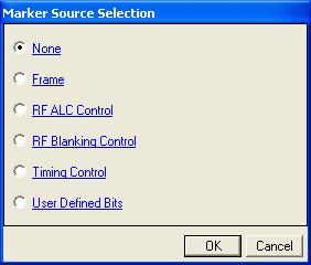
None
Sets all maker points are
set to zero (inactive).
Frame
Sets the first five marker bits of the frame to 1, which sets an active
marker for the first five waveform samples (waveform points). The signal
generator outputs the Marker 1 output from the rear-panel Event 1 output.
RF ALC Control
Activates the automatic leveling control (ALC) function. When enabled,
the ALC constantly monitors and controls the RF output power of the signal
generator.
The ALC circuit cannot properly handle some modulation conditions, leading
to output power level errors. In these conditions, turning the ALC off
and using the signal generator power search function can achieve better
power level accuracy.
RF Blanking
Control
Assigns a specific marker to activate RF blanking. The automatic leveling
control (ALC) hold is automatically enabled during output blanking.
RF Blanking Control improves the signal quality when the MAC channel
and/or traffic channel are de-activated in a timeslot. It does so by increasing
the on/off ratio of the forward link RF bursts.
When RF Blanking Control is enabled, the marker polarity must be set
to positive or the wanted RF signal will be blanked, resulting in no RF
output from the signal generator.
Timing Control
This marker is generated by the waveForm. IS95/2000 generates the first
five waveform samples (waveform points) in the cycle. 1xEV-DO generates the half-slot timing.
User
Defined Bits
Opens the user  data entry area,
which lets you customize the marker signal.
data entry area,
which lets you customize the marker signal.
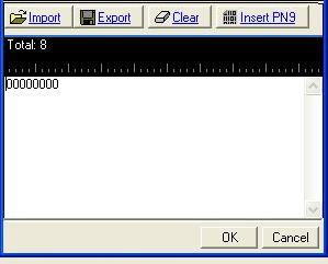
The user data area contains
buttons to import, export, or clear user marker data along with the ability
to insert a PN9 sequence as the marker bits. Optionally you can manually
insert or delete marker data. To manually insert marker data, simply place
the cursor within the data entry area or highlight existing bits, and
insert bits. There are three ways to insert marker data:
-
using
the 1 (marker active) and 0 (marker inactive) keys on the keyboard
-
using
the Insert PN9 button
-
pasting data from a file
or from within the current view
(The key board shortcuts
Ctrl+C and Ctrl+V work for user data entry.)
To delete data, simply
place the cursor at the desired location within the data or highlight
bits, and delete data. The key board short cut Ctrl+Z also deletes highlighted
data.
The maximum number of marker
bits for the user data entry area is 2,097,152 which equals 32,768 (1short
code data points) * 64 (oversampling ratio). This is also the maximum
file size.
The four buttons in the
expanded area are:
Import
Loads a user-defined pattern from a selected
location. When you select this button, the Open user defined data dialog
box appears for navigating to and selecting the desired file. An imported
file automatically updates the user data entry area. The software accepts
the following file types:
The maximum file size is 2,097,152 bits. If the imported file is larger
than bits, the software truncates the bits to conform
to the maximum file size.
Export
Saves the current data pattern, showing
in the user data entry area, to a file. When you select this button, a
Save user defined data dialog box appears for navigating to the location
where you can save the file. The software saves the user data as one of
the following selected file types:
Clear
Clears all data showing in the user data entry area.
Insert PN9
Inserts a fixed pattern pseudo-random bit sequence containing 511 bits
(29–1)
into the user data entry area. The software generates this fixed pattern
in accordance with the CCITT recommendation O.153. Repeated clicking of
this button adds additional PN9 sequences until the software attains the
maximum file size of bits. The software truncates
data in excess of the maximum file size.
To edit the data pattern, insert the cursor at the desired point in
the file and click Insert PN9, or enter the information manually using
the keyboard keys 1 and 0. The software inserts the data at the cursor
position and truncates all data in excess of 2,097,152 bits.
The software lets you create a file larger than it uses for the waveform.
When this occurs, the software truncates the excess marker bits. Conversely,
if there are not enough marker bits, the software repeats the marker bit
pattern until there are enough marker bits to match the Total Sample Points
cell value.