When Reference is the selected Packet Type and CTEInfo Present is set to True, the CTE Info Setting properties appear.
Choice: Single Packet | Multiple Packet
Default: Single Packet
Double-click or use the drop down menu to select the distribution type of packet payload.
When Single Packet is selected, the software creates a waveform that consists of one Bluetooth packet. When downloaded to the signal source, the waveform is repeatedly played back resulting in a packet sequence comprised of identical packets. When Multi Packet is selected, the software creates a waveform that consists of a multiple packet sequence. A data pattern is distributed into the payload portion of each packet in the sequence. Once downloaded to the instrument, the signal generator repeatedly plays back the entire packet sequence. The net result is the ability to configure longer data sequences for analysis.
Choice: PN9 | S11110000 | S10101010 | S11111111 | S00000000 | S00001111| S01010101 | PN15 | User Defined
Default: PN9
Click  to set the data type of the packet payload:

When continuous (Data Continuous is set to ON) or is selected, the software automatically configures the Length and Repetitions fields. The number of packets required to accommodate the selected continuous PN pattern is also automatically determined and updated the number of bit
When change the payload data type to PN or fixed byte pattern, the payload header byte will update according to the payload content field table below:
|
Payload Content Field |
Payload Description |
|---|---|
|
0000 |
PRBS9 sequence |
|
0001 |
Repeated ’11110000’ sequence |
|
0010 |
Repeated ’10101010’ sequence |
|
0011 |
PRBS15 sequence – reserved for future use |
|
0100 |
Repeated ’11111111’ sequence - reserved for future use |
|
0101 |
Repeated ’00000000’ sequence - reserved for future use |
|
0110 |
Repeated ’00001111’ sequence - reserved for future use |
|
0111 |
Repeated ’01010101’ sequence - reserved for future use |
If is selected as the data pattern, the number of bits, shown in the Data Length field, equals s in the user data file, up to the number of bits allowed for that packet type. Any remaining bits in the user data file beyond the maximum amount will be truncated.
Choice: PN9 | PN15 | User Defined
Default: PN9
Click
to set the data type of the packet payload:
When continuous (Data Continuous is set to ON) or is selected, the software automatically configures the Length and Repetitions fields. The number of packets required to accommodate the selected continuous PN pattern is also automatically determined and updated. the number of bit.
If is selected as the data pattern, the number of bits, shown in the Data Length field, equals s in the user data file, up to the number of bits allowed for that packet type. Any remaining bits in the user data file beyond the maximum amount will be truncated.
Choice: On | Off
Default: On
Double-Click or use the drop-down menu to set the continuous state of the packet payload data.
This setting is only available when Payload Distribution is set to Multiple Packet.
Set the repetition number of the packet payload data.
This setting is only available when Payload Distribution is set to Multiple Packet and Data Continuous is set to Off.
Set the number of total bits contained in the payload data.
This setting is only available when Payload Distribution is set to Multiple Packet and Data Continuous is set to Off.
Display the number of full packet occupied by the packet payload.
Display the number of partial packet occupied by the packet payload. Because the payload portion of each packet is filled to capacity if possible, the number of partial packets appended to the end of a packet sequence will always be 0 or 1.
Choice: 0 | 1
Default: 0
Sets the number of padding packets occupied by the packet payload.
This property table appears only when Packet Type is set to Reference and CTEInfo Present is set to True.
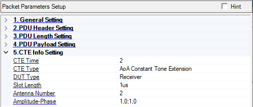
Range: 2 to 20
Default: 2
Set the CTE Time field of CTE Info Header to indicate the length of the Constant Tone Extension in units of 8 us.
Choice: AoA Constant Tone Extension | AoD Constant Tone Extension with 1 us slots | AoD Constant Tone Extension with 2 us slots
Default: AoA Constant Tone Extension
Coupling: If the CTE Type is set to AoA Constant Tone Extension, the Slot Length will be visible, otherwise will hide
Set the CTE Type field of CTE Info Header to indicate the type of the Constant Tone Extension and duration of the switching slots.
Choice: Receiver | Transmitter
Default: Receiver
Coupling: For the transmitter, the Slot Length, Antenna Number, and Amplitude-Phase parameters are not available.
Set the DUT type to indicate that the IQ sampling is at Receiver or Transmitter.
For the receiver,a continuous wave at the carrier frequency will be sent in the switch slot.
For the transmitter, the switch slot will be idle for AoD, and continuous transmission for AoA.
Choice: 1us | 2us
Default: 1us
Set the slot length for AoA when the packet contains the Constant Tone Extension field.
Range: 2 to 4
Default: 2
Coupling: It determines the number of rows in the Antenna Configuration dialog
Set the number of antennas the packet contains the Constant Tone Extension field.
Range:
Amplitude (ratio): 0.5 to 2
Phase: -180 to 180 degree
Default: 1,0;1,0
Coupling: The number of pairs of the Amplitude-Phase is consistent with the value of AntNum
Opens a dialog where you can set the Amplitude-Phase characteristics applied to each antenna.
The amplitude value is expressed as a ratio.
The phase value is expressed in degrees.