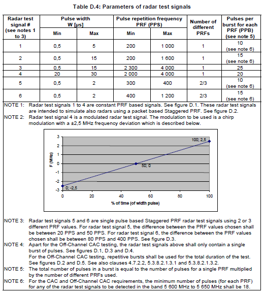
Source: ETSI EN 301 893 v1.7.1
| 1. Basic | 2. Signal Configuration | 3. Burst Configuration |
|---|---|---|
Displays the trial ID range included in the current ETSI 301 893 radar profile.
Range: 1 to 200
Default: 20
Couplings: Setting Number of Trials here has the same effect as setting Number of Trials in the corresponding row of the trial list setting table under DFS node.
Enter the number of trials for the current ETSI radar profile.
Range: 0.0 ~ 600.0 s
Default: 0.0 s
Set the interval time between trials.
Choices: Reference | Type 1 | Type 2 | Type 3 | Type 4 | Type 5 | Type 6
Default: Reference
Couplings: Setting Radar Type here has the same effect as setting Radar Type in the corresponding row of the trial list setting table under DFS node.
Select a radar type for the current ETSI radar profile. For the detailed description of each type, refer to ETSI Radar Profiles.
This cell is read only. It displays the selected standard version for a specific Radar Profiles.
Choices: Others| 5600 MHz to 5650 MHz
Default: Others
Couplings: This cell is only visible when the Standards of Radar Profiles is selected to be ETSI 301 893.

Source: ETSI EN 301 893 v1.7.1
Set the Operating Frequency Band to 5600 MHz to 5650 MHz when making CAC and Off-Channel CAC requirements test in 5600 MHz to 5650 MHz band. For other test cases, set Operating Frequency Band to Others.
Range: 1 to 144; Actually, the maximum number of bursts depends on the capability of the connected instrument and the Radar Type.
Default: 1
Couplings: Setting Number of Bursts here has the same effect as setting the Number of Bursts in the corresponding row of the trial list setting table under DFS node.
Defines the number of bursts in a trial.
Value: False | True
Default: False
Sets whether to use variable burst interval time.
False - This is the default selection and is intended for backwards compatibility.
True - The burst interval times (BIT) of different bursts will be randomly generated, based on the min/max range. In the Trial List Table, you can click the ‘+’ to see the actual BITs for different bursts, and you can change a certain BIT to a different value (but should still remain within the min/max range).
Range: 45.0 s to 60.0 s
Default: 45.0 s
Couplings: This parameter is read only and is only displayed when Variable Burst Interval Time is set to True.
Displays the variable burst interval time (BIT).
Displays the upper limit of the range.
Displays the lower limit of the range.
Displays the resolution of random value selection.
Range: 0 to 600 s
Default: 0 s
Couplings:
Setting Interval Between Bursts here has the same effect as setting Interval Between Bursts in the corresponding row of the trial list setting table under DFS node.
This parameter is read only and is only displayed when Variable Burst Interval Time is set to False.
Enter the interval time between bursts. For the concept of the interval time between bursts, refer to ETSI 301 893 Radar Profiles.
Displays the pulse width. If the pulse width of the selected radar type is a range instead of a fixed value, another three parameters will be displayed under this cell, step, min, and max.
Displays the upper limit of the range.
Displays the lower limit of the range.
Displays the resolution of random value selection.
Displays the Pulse Repetition Frequency (PRF). If the PRF of the selected radar type is a range instead of a fixed value, another three parameters will be displayed under this cell, step, min, and max.
Displays the upper limit of the range.
Displays the lower limit of the range.
Displays the resolution of random value selection.
Displays the number of different PRFs in a burst for the selected radar type.
Displays the number of pulses for each PRF in one burst.
This cell is only visible when Radar Type is set to type 4 and it displays the bandwidth of the chirp radar signal,
This cell is only visible when Radar Type is set to type 5 or type 6 and it displays the way that the pulses with different PRFs are arranged. For details about single pulse based and signal packet based, refer to ETSI 301 893 Radar Profiles.
This cell is only visible when Radar Type is set to type 5 or type 6 and it displays the difference between PRFs.
In ETSI radar profiles, type 5 and type 6 use 2 or 3 different PRF values. For type 5, the difference between PRF values shall be chosen between 20 and 50 Hz. For type 6, the difference between PRF values shall be chosen between 80 to 400 Hz.
Displays the upper limit of the range.
Displays the lower limit of the range.
Displays the resolution of random value selection.