The Waveform Name and Comments parameters no longer appear in this new model (N7608C) of the software. The waveform name is now fixed to 'CustomModulation.' If you recall a settings file (.scp) from the previous model (N7608B), the waveform name will also be changed to 'CustomModulation.'
Opens a drop-down menu where you can quickly access preset configurations for a specific application. (See table of selections below.)
|
Cellular |
LTE |
LTE: Downlink 5MHz LTE: Uplink 5MHz |
|
|
Wireless Networking |
WLAN |
WLAN: IEEE 802.11e |
|
|
ZigBee |
BPSK O-QPSK |
||
|
Wi-SUN(802.15.4g) |
2-FSK 50/1 2-FSK 100/0.5 |
||
|
ITU-T G.9959 |
R2-40 kps R3-100 kps |
||
|
802.15.3d |
|||
|
Digital Video
|
DVB-T/H |
DVB-T/H 2K 1/8 |
|
|
ISDB-T |
ISDB-T (Model3, 1+12) |
||
|
DOCSIS |
DOCSIS 3.1 Upstream DOCSIS 3.1 Downstream |
||
|
DVB-S2
|
QPSK |
||
|
8PSK |
|||
|
16APSK |
4+12APSK 2/3 4+12APSK 3/4 4+12APSK 4/5 4+12APSK 5/6 4+12APSK 8/9 4+12APSK 9/10 |
||
|
32APSK |
4+12+16APSK 3/4 4+12+16APSK 4/5 4+12+16APSK 5/6 4+12+16APSK 8/9 4+12+16APSK 9/10 |
||
|
DVB-S2X
|
8APSK |
2+4+2APSK 100/180 2+4+2APSK 104/180 |
|
|
16APSK |
4+12APSK 26/45 4+12APSK 3/5 4+12APSK 28/45 4+12APSK 23/36 4+12APSK 25/36 4+12APSK 13/18 4+12APSK 140/180 4+12APSK 154/180 4+12APSK 7/15 4+12APSK 8/15 4+12APSK 26/45 4+12APSK 3/5 4+12APSK 32/45 8+8APSK 90/180, 96/180, 100/180 8+8APSK 18/30 8+8APSK 20/30 |
||
|
32APSK |
4+12+16APSK 2/3 4+12+16APSK Short 2/3 4+12+16APSK Short 32/45 4+8+4+16APSK 128/180 4+8+4+16APSK 132/180 4+8+4+16APSK 140/180 |
||
|
64APSK |
16+16+16+16APSK 128/180 8+16+20+20APSK 7/9 8+16+20+20APSK 4/5 8+16+20+20APSK 5/6 4+12+20+28APSK 132/180 |
||
|
128APSK |
128APSK 135/180 128APSK 140/180 |
||
|
256APSK |
256APSK 116/180 256APSK 124/180 256APSK 128/180 256APSK 135/180 256APSK 20/30 256APSK 22/30 |
||
|
Land Mobile Radio
|
APCO25 |
C4FM CQPSK HCPM HDQPSK |
|
|
TETRA |
|||
|
NXDN |
4800bps 9600bps |
||
|
dPMR |
|||
|
DECT |
|||
|
DMR |
|||
|
ARIB |
T98 T61 T102 |
||
|
Broadcast Radio
|
DAB |
DAB Mode I |
|
|
CDR |
CDR TxMode 1, Spectrum Mode 2 CDR TxMode 1, Spectrum Mode 9 CDR TxMode 1, Spectrum Mode 10 |
||
|
DRM |
DRM: ModeB 20K DRM: ModeB 9K DRM: ModeA 9K |
||
Opens a drop-down menu where you can quickly access preset configurations for a specific modulation type. (See table of selections below.)
|
OFDM |
|
|
FBMC OQAM |
|
|
UFMC |
|
|
GFDM |
|
|
F-OFDM |
|
|
QAM & ASK & PSK |
2ASK BPSK QPSK 16QAM 64QAM 256QAM |
|
FSK |
2FSK 4FSK 8FSK 16FSK 32FSK 64FSK MSK |
|
SOQPSK |
SOQPSK-TG (IRIG 106-04) SOQPSK-A SOQPSK-B |
|
ARTM Multi-h CPM |
|
|
Analog Modulation |
AM FM PM |
|
Radar |
FMCW Radar MFSK Radar Customized Chirp |
|
Channel Sounding |
|
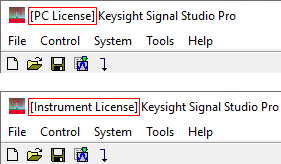
Choices: PC License | Instrument License
Default: PC License.
Select the playback license mode. If no PC license is available, only Instrument License can be used.
|
|
N76xxAPPC |
N76xxEMBC |
|
|
License File Presence |
PC (running Signal Studio Pro software) |
Signal Generator |
|
|
Playback License Mode |
Two selections (PC License | Instrument License) |
One selection (Instrument License) |
|
|
Available Software Functions |
Live Connection to Signal Generator |
ü |
ü |
|
VSA .SETX Export |
ü |
ü |
|
|
Programming API |
ü |
ü |
|
|
Waveform Export |
ü |
ü |
|
You can switch waveform playback license mode to take advantage of an instrument license, even when a PC license is available with GUI parameter "Playback License Mode" under "Waveform Setup" node, "Basic" group.
Playback License Mode has 2 selections: PC License | Instrument License
When "PC License" is selected, "Waveform Name" should be hidden (you cannot change the waveform name). And Waveform Name API is read-only (not accepting waveform name change).
When valid PC license (N7608APPC) exists, this parameter is active and you can choose either one. Default is "PC License."
When valid PC license does NOT exist, this parameter is read-only and "Instrument License" mode is selected.
Window ![]() caption displays "[PC License]" or "[Instrument License]" to indicate the currently selected license mode.
caption displays "[PC License]" or "[Instrument License]" to indicate the currently selected license mode.
Default (or base value): 2023.0801
Read-only. This value will update based on the feature’s required license version.
Choices: Custom IQ | Custom OFDM | 5G Candidate
Default: Custom OFDM
Select the custom modulation format of the waveform. The tree view nodes and associated properties in the parameter view change with each selection.
Custom IQ: Single carrier signal with user-defined IQ constellations.
Custom OFDM: Multicarrier signal based on OFDM with user-defined settings.
5G Candidate: Multicarrier signal with 5G PHY scheme.
Range: 1 to 300
Default: 1
Enter the number of frames included in the waveform.
Choices: On | Off
Default: Off
Enable or disable the User Defined Sample Rate, if enabled, the OverSamplingRatio will not be used.
User defined sample rate is not applicable for Radar signal.
Range:
OFDM/F-OFDM: 1 to 1024
Others: 2 to 1024
Default:
Custom IQ: 32
Custom OFDM: 4
5G Candidate: 4
Enter the oversampling ratio of the waveform. The Total Sample Points is automatically determined based on the oversampling ratio.
Oversampling Ratio is not applicable for Radar signal.
Range: 100 MHz to 100 GHz
Default: 200 MHz
Set the value of user defined sample rate if user defined sample rate is enabled.
Displays the generated waveform length in sample points. This value is read-only and automatically updates with changes to oversampling ratio, number of frames, and custom modulation type.
Displays the generated waveform length in seconds. This value is read-only and automatically updates with changes to oversampling ratio, number of frames, and custom modulation type.
Choices: On | Off
Default: Off
Enable or disable the mirror spectrum (inverted IQ) for the waveform.
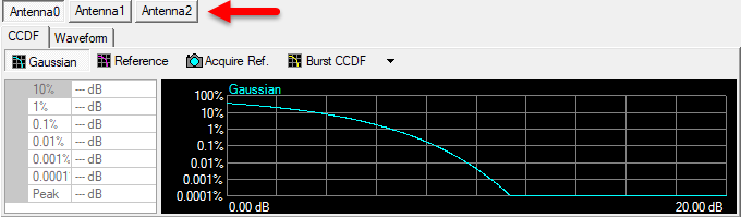
Range: 1 to 8
Default: 1
Enter the number of antennas included in the waveform,
When the Number of Antennas is larger than or equal to 2, each antenna’s CCDF and waveform plots are figured individually.
Choices: Waveform Start | Frame Start | RF Blanking Control | RF ALC Control
Default: Waveform Start
Select the source for marker 1.
Waveform Start: It indicates the beginning of the waveform.
Frame Start: It indicates the beginning of each frame in the waveform.
RF Blanking Control: It indicates the burst part in the waveform.
RF ALC Control: It indicates the part used for ALC control in the waveform.
Choices: Waveform Start | Frame Start | RF Blanking Control | RF ALC Control
Default: Frame Start
Select the source for marker 2.
Waveform Start: It indicates the beginning of the waveform.
Frame Start: It indicates the beginning of each frame in the waveform.
RF Blanking Control: It indicates the burst part in the waveform.
RF ALC Control: It indicates the part used for ALC control in the waveform.
Default: RF Blanking Control
Displays the source for marker 3. RF Blanking Control is always used as Marker 3 source.
Default: RF ALC Control
Displays the source for marker 4. RF ALC Control is always used as Marker 4 source.
Choices: On | Off
Default: Off
Enable or disable the crest factor reduction for the waveform. When enabled, peak cancellation algorithm is used to subtract a weighted version of the cancellation pulses from the original input signal. It strikes a balance between the out-of-band emission and in-band waveform quality when reducing the PAPR of the signal.
Crest Factor Reduction is always visible and configurable under Waveform Setup, however, supporting parameters appear only when Crest Factor Reduction is enabled. If the waveform PAPR is already lower than the target level, then no processing will be performed on the original waveform.
Range: 3 to 100 dB
Default: 8 dB
Set the PAPR value to achieve after crest factor reduction.
Range: 1 to 20
Default: 10
Specify the maximum times of iteration.With the increasing of iteration, the PAPR value should converge to a steady level.
Range: 0 to 100%
Default: 100%
Specify the percentage that the cancellation pulses can be removed.
Range: 20 to Waveform Total Sample Points
Default: 1000
Block is the range that a single cancellation pulse can be identified. If the waveform length is L, and the block size is B, then the number of blocks is N=floor(L/B)+1. Therefore, there will be N pulses at most to be removed.
Opens the ![]() Filter Mask for Crest Factor Reduction editor to define a filter response in frequency domain. In the table, the frequency points must be entered with an order of increasing frequency in unit of MHz, and its corresponding amplitude is in unit of dB. When generating this filter mask, the frequency points between the specified points are linearly interpolated. When signal symbol rate is changed, this table will be automatically updated. User may need to adjust the mask manually to fit the signal bandwidth.
Filter Mask for Crest Factor Reduction editor to define a filter response in frequency domain. In the table, the frequency points must be entered with an order of increasing frequency in unit of MHz, and its corresponding amplitude is in unit of dB. When generating this filter mask, the frequency points between the specified points are linearly interpolated. When signal symbol rate is changed, this table will be automatically updated. User may need to adjust the mask manually to fit the signal bandwidth.
The format of Filter Mask string, appearing in the parameter field, is: <freq 1>,<amp 1>; <freq 2>,<amp 2>;….<freq n>,<amp n>.
Choices: On | Off
Default: Off
Enable or disable the multicarrier mode for waveform generation, when enabled, waveform which has at least one carrier will be generated, the count of carriers is decided by the frequency offsets definition, When disabled, waveform with only one carrier will be generated.
Indicate how many carriers has been defined and is a read only value.
Choices: Fixed | Random
Default: Random
Define the initial phase of every carrier when multicarrier mode enabled. “Fixed” means all carriers has same initial phase which is zero; “Random” means initial phase of every carrier is random value.
This feature requires license version 2024.0801 or later.
Choices: On | Off
Default: Off
Supported for multicarrier mode with Custom OFDM.
It’s default to Off to be backwards compatible, so every carrier read from the beginning of the IQ Values/Payload data bits. When it turns On, the IQ Values/Payload data bits will be used as a circular buffer for multi-carriers continuously. The IQ Values for Multi-Carriers string parameter to be used with Continuous Payload On and user can manually configure the desired values. IQ Values for Multi-Carriers is available for Preamble and Pilot (Pilot Data Mode is IQ Values).
Also, Saving VSA 89600 Setup will automatically generate multiple SETX files for multi-carriers.
Range: 0 to 65535
Default: 0
Define the payload data offset between each carriers when multicarrier mode enabled, it is only applied for Custom IQ.
Opens a window where you can define the frequency offset of every carrier for multicarrier mode. There are three methods that can be used:
To configure by individual carrier, use "," as delimiter. For example: "1MHz,2MHz,10MHz,20MHz" as frequency offsets for 4 carriers.
To configure by a range of carriers, use ":" to define the start frequency offset of first carrier, frequency step and the count of multi carriers. For example,"1MHz:2MHz:5" means 5 carriers offsets defined as "1MHz,3MHz,5MHz, 7MHz,9MHz"
Above 2 ways can be used by combination. For example: "1MHz:2MHz:5, 20MHz,30MHz"
Opens a window where you can define the power offset of every carrier for multicarrier mode. There are three methods that can be used:
To configure by individual power offsets, use "," as delimiter. For example: "0,-1,0,-1" means the power offset for 1st carrier is 0 dB , -1dB for 2nd carrier,0dB for 3rd carrier and -1dB for 4th carrier.
To configure by a range of power offsets, use ":" to define the power offset of first carrier, power offset step and the count of multi carriers. For example,"0:-1:5" means "0,-1,-2, -3,-4".
Above 2 ways can be used by combination. For example: "0:-1:5, -8,-9".
The count of final power offsets definition is also decided by value of frequency offsets, because they need to have same count.
Unit is dB.
Choices: On | Off
Default: Off
Coupling: Coupled with VSA Equalization Data File and Equalization Bandwidth.
Enable or disable equalization for waveform generation. When enabled, equalization will be applied to the generated waveform according to the EQ Data from VSA.
Choices: The file type should be .csv
Load the EQ data file from VSA. You can type out the directory of the EQ file or browse it in your computer.
Range: The equalization bandwidth should not be larger than the sampling rate of the waveform
Coupling: Coupled with the sampling rate of the waveform
The equalization will be performed within this bandwidth.
The graph view displays several different representations of the generated waveform. For more information, see Graph View.