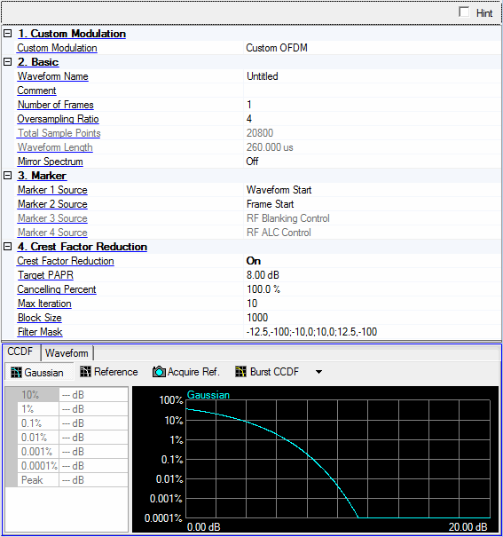

Choices: Custom IQ | Custom OFDM | 5G Candidate
Default: Custom OFDM
Select the custom modulation format of the waveform. The tree view nodes and associated properties in the parameter view change with each selection.
Custom IQ: Single carrier signal with user-defined IQ constellations.
Custom OFDM: Multicarrier signal based on OFDM with user-defined settings.
5G Candidate: Multicarrier signal with 5G PHY scheme.
Enter an alpha-numeric waveform file name of up to 22 characters. (If you enter a name with more than 23 characters, the software truncates the name to 22 characters when you click outside of the cell.) The name can include spaces and the following special characters: _ $ & # + - [ ].
Enter an alpha-numeric comment of up to 32 characters. The comment resides in the file header and can include spaces and special characters.
Range: 1 to 300
Default: 1
Enter the number of frames included in the waveform.
Range: 2 to 16
Default: 4
Enter the oversampling ratio of the waveform. The Total Sample Points is automatically determined based on the oversampling ratio.
Displays the generated waveform length in sample points. This value is read-only and automatically updates with changes to oversampling ratio, number of frames, and custom modulation type.
Displays the generated waveform length in seconds. This value is read-only and automatically updates with changes to oversampling ratio, number of frames, and custom modulation type.
Choices: On | Off
Default: Off
Enable or disable the mirror spectrum (inverted IQ) for the waveform.
Choices: Waveform Start | Frame Start | RF Blanking Control | RF ALC Control
Default: Waveform Start
Select the source for marker 1.
Waveform Start: It indicates the beginning of the waveform.
Frame Start: It indicates the beginning of each frame in the waveform.
RF Blanking Control: It indicates the burst part in the waveform.
RF ALC Control: It indicates the part used for ALC control in the waveform.
Choices: Waveform Start | Frame Start | RF Blanking Control | RF ALC Control
Default: Frame Start
Select the source for marker 2.
Waveform Start: It indicates the beginning of the waveform.
Frame Start: It indicates the beginning of each frame in the waveform.
RF Blanking Control: It indicates the burst part in the waveform.
RF ALC Control: It indicates the part used for ALC control in the waveform.
Default: RF Blanking Control
Displays the source for marker 3. RF Blanking Control is always used as Marker 3 source.
Default: RF ALC Control
Displays the source for marker 4. RF ALC Control is always used as Marker 4 source.
Choices: On | Off
Default: Off
Enable or disable the crest factor reduction for the waveform. When enabled, peak cancellation algorithm is used to subtract a weighted version of the cancellation pulses from the original input signal. It strikes a balance between the out-of-band emission and in-band waveform quality when reducing the PAPR of the signal.
Crest Factor Reduction is always visible and configurable under Waveform Setup, however, supporting parameters appear only when Crest Factor Reduction is enabled. If the waveform PAPR is already lower than the target level, then no processing will be performed on the original waveform.
Range: 3 to 100 dB
Default: 8 dB
Set the PAPR value to achieve after crest factor reduction.
Range: 0 to 100%
Default: 100%
Specify the percentage that the cancellation pulses can be removed.
Range: 1 to 20
Default: 10
Specify the maximum times of iteration.With the increasing of iteration, the PAPR value should converge to a steady level.
Range: 20 to Waveform Total Sample Points
Default: 1000
Block is the range that a single cancellation pulse can be identified. If the waveform length is L, and the block size is B, then the number of blocks is N=floor(L/B)+1. Therefore, there will be N pulses at most to be removed.
Opens the  Filter Mask for Crest Factor Reduction editor to define a filter response in frequency domain. You can add, remove, and edit the filter mask for generating the cancelling pulses. The frequency points (in MHz) must be entered in ascending order with the corresponding amplitude (in dB). When generating the filter mask, the frequency points between the specified points are linearly interpolated. When the signal symbol rate is changed, the table updates automatically. You may need to adjust the mask manually to fit the signal bandwidth.
The format of Filter Mask string, appearing in the parameter field, is: <freq 1>,<amp 1>; <freq 2>,<amp 2>;….<freq n>,<amp n>.
The graph view displays several different representations of the generated waveform. For more information, see Graph View.