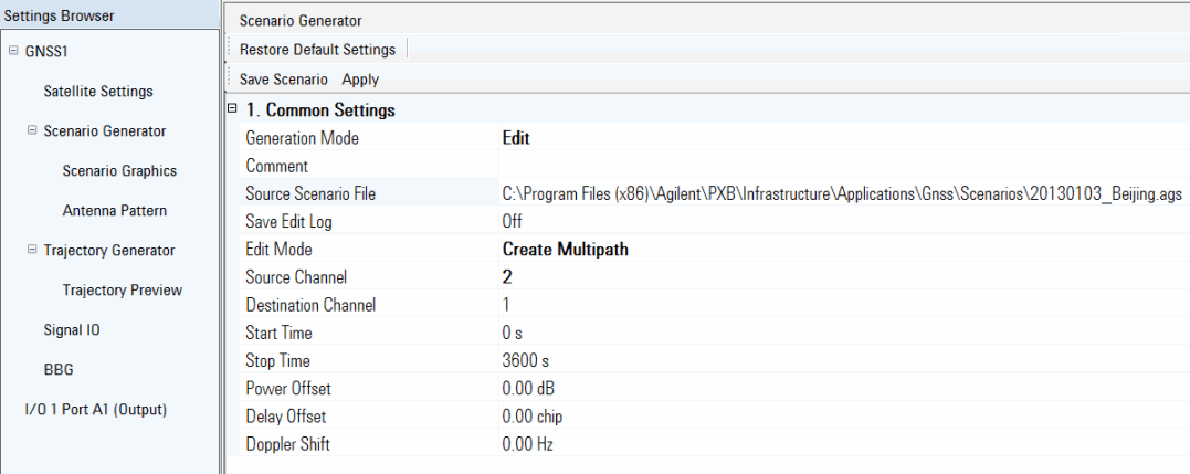
This procedure guides you through the settings to edit a scenario using the tab on the software user interface (UI). To learn more about individual cell settings, refer to the UI descriptions.
Editing a scenario applies only to stored scenario files.

To view a list of the completed edits through the UI, see the log at the bottom of the view in the Scenario Graphics tab.
Load a PXB GNSS configuration:
If you already have a GNSS configuration loaded on the PXB, skip the following substeps and proceed to Step 2.
Open the PXB Baseband Generator and Channel Emulator software.
Under Generate in the Configuration Browser, select either a single- or dual-channel configuration.
For each of the channels in the block diagram, click the drop-down arrow in the  waveform block, and in the dialog box that appears, use the drop-down menu to select (Global Navigation Satellite System). ARB on the waveform block changes to GNSS.
In the dialog box, click
 Assign an MXG/EXG/ESG signal generator to the output block
for each channel along with selecting the IO Port and IO Port Type.
In the dialog box, click
Click .
In the Settings Browser, select and ensure the tab is active, if not, select it.
Notice that the software starts with as the default Generation Mode.
Click and from the drop down menu, select .
Click
the cell,
and use the dialog box button  to launch the
dialog box for navigating to and selecting the scenario file to edit.
If there is a desire to keep track of the edits, click the cell, and from the drop down menu, select .
The software saves the log file with the same name (uses .log extension) and at the same location as the edited scenario file when you click the Save Scenario button.
Click and from the drop down menu, select the mode:
The settings that follow the cell change based on this cell's selection.
Finish configuring the settings for the selected Edit Mode:
To  Trim
Trim
To make further edits using another mode, repeat Steps 10 and 11.
When all changes have been made, click the button to launch the dialog box for selecting a location and saving the file.