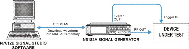
This example shows you how to set up the equipment and configure the N7612C Signal Studio for TD-SCDMA/HSPA 2018 software to create a single carrier TD-SCDMA waveform in Basic Capability for a typical Downlink EVM measurement for composite and code domain. The parameters used in this example are based on the 3GPP TS 25.142 parameters requirement of the BS transmitted signal for EVM modulation accuracy testing.
The Composite EVM measures the EVM of a multi-code channel signal. It is valuable for evaluating the quality of the transmitter for multi-code channel signals, detecting spreading or scrambling errors, identifying certain problems such as I/Q swap between the RF and baseband sections, and analyzing errors that caused by high interference in the signal.
The code domain EVM measurement is used to get the indication of the modulation quality at the chip level for a single-channel signal. It can detect baseband filtering, modulation, and RF impairments, but does not detect spreading or scrambling errors.
In this example, an N5182A MXG signal generator is used to achieve the best EVM performance and the Signal Studio for TD-SCDMA/HSPA software generates the waveform based on the waveform, carrier, timeslot/channel parameters configuration, and then downloads the waveform into the signal generator.
Click in the tree view (left pane of the main window) to configure waveform parameters. The parameter view (right pane) now displays the Carrier Configuration Summary table and the Waveform Setup section. The Waveform Setup section contains the key waveform related parameters.
Add one Basic Carrier: You have the option of adding either a Basic or Advanced carrier to the current carrier selection showing in the configuration summary table.
In
the configuration summary table, click the Add new carrier button  .
.
Select from the drop-down menu.
Make sure you have one Basic Carrier listed in the table.
Set the waveform parameters:
: Set the waveform name as desired. The name you define here is displayed on the signal generator when you download the waveform.
: Set to 3 for this example so that the TS4, TS5 and TS6 are downlink timeslots.
: Select Root Raised Cosine, set Alpha = 0.22, Length = 64 symbol for this example. You can set other filter types as desired.
Leave all other parameters settings at their default values.
Now you can see the  basic carriers
displayed in the tree view. Click the carrier node in the tree view to
set the carrier parameters. The Carrier Setup in the parameter view displays
the baseband and 3GPP parameters for that carrier.
basic carriers
displayed in the tree view. Click the carrier node in the tree view to
set the carrier parameters. The Carrier Setup in the parameter view displays
the baseband and 3GPP parameters for that carrier.
For each carrier, click each timeslot under that carrier in the tree view to configure the timeslot parameter. Enable the state of the downlink timeslots TS0, TS4, TS5, TS6.
Enable the state of the Downlink Pilot Timeslot (DwPTS) and disable the state of the Uplink Pilot Timeslot (UpPTS).
Leave all other parameters setting at their default values for each timeslot in each carrier.
Click each timeslot in the tree view to configure the Resource Unit Allocation. The parameter view now displays the Resource Unit Setup tables.
For TS0, Enable ( ) the state for RUs index from 1 to 2.
For downlink timeslots TS4, TS5 and TS6, Enable ()
the state for RUs index from 1 to 10.
For uplink timeslots TS1, TS2, TS3, make sure all of the RUs States are off.
Leave all other parameters setting at their default values for each RU in the timeslot.
Click in the tree view. The parameter view now shows seven panes: Configuration, Basic, I/Q, ALC, Dual ARB, Dual ARB Marker Utilities, and Dual ARB trigger.
: Under Basic Pane, set it to 2 GHz.
: Under Basic Pane, set it to -8 dBm for this example
Click Generate a waveform button  in the tool bar. The software generates an
I/Q waveform file in accordance with the current waveform configuration
and signal generation setup. Waveform generation time varies proportionally
to the complexity of the waveform.
in the tool bar. The software generates an
I/Q waveform file in accordance with the current waveform configuration
and signal generation setup. Waveform generation time varies proportionally
to the complexity of the waveform.
After the waveform is generated, you can examine its characteristics.
View the CDP graph for the carrier based on the configuration by clicking the carrier in the tree view. For more information, refer to CDP Graph.
By clicking in the tree view, you can view plots of the baseband spectrum, I and Q signals, and CCDF curve prior to downloading the file to the signal generator. For more information, refer to CCDF Graph and Waveform Graph.
To download the waveform file to the signal generator,
click Download  in the tool bar if you have configured the instrument connection.
The signal generator automatically begins to play the TD-SCDMA waveform.
Local control of the signal generator is re-enabled by pressing the hardkey, allowing signal generator
settings to be modified from the front panel. The waveform file, however,
cannot be modified after downloading it to the signal generator.
in the tool bar if you have configured the instrument connection.
The signal generator automatically begins to play the TD-SCDMA waveform.
Local control of the signal generator is re-enabled by pressing the hardkey, allowing signal generator
settings to be modified from the front panel. The waveform file, however,
cannot be modified after downloading it to the signal generator.