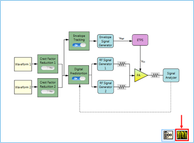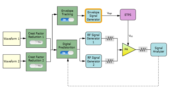
The following figure shows the block view settings in N7614C for a dual-band ET measurement.
The remaining section of this topic provides an example procedure of setting N7614C for DPD measurement. Note that for different PA, the settings are different. But there is normally total 10 typical steps to set all related parameter before executing measurement.
Step 1: Set the Waveform Blocks
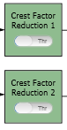
Step 2: Set the Crest Factor Reduction Blocks
Step 3: Set the Digital Predistortion Block
Step 4: Set the RF Signal Generator Blocks
Step 6: Set the Signal Analyzer Block
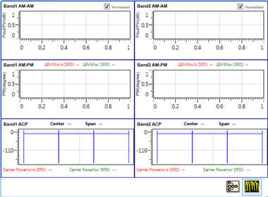
Step 7: Set the Measurement View
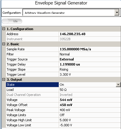
Step 8: Set the Envelope Signal Generator Block
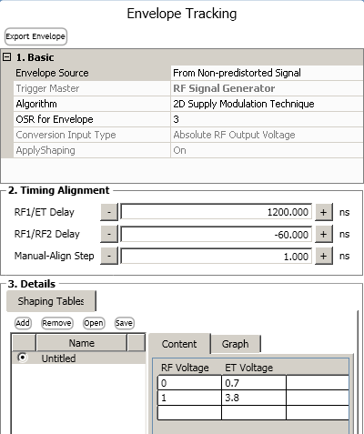
Step 10: Set the Envelope Tracking Block
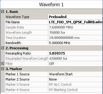
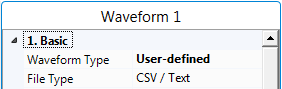
Click on the Waveform 1 block icon on the UI. In the ![]() right panel, select Preloaded as the Waveform type and select the "LTE_FDD_5M_QPSK_FullRB.wfm" file, set the Bandwidth to 5 MHz according to the waveform bandwidth.
right panel, select Preloaded as the Waveform type and select the "LTE_FDD_5M_QPSK_FullRB.wfm" file, set the Bandwidth to 5 MHz according to the waveform bandwidth.
If you are using a MATLAB script, select User-defined for this step.
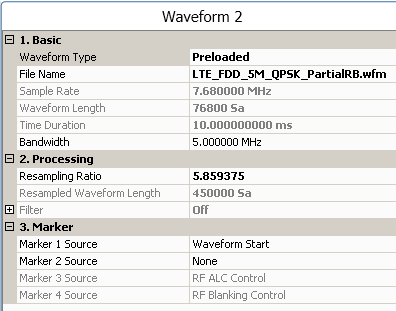
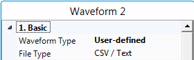
Click on the Waveform 2 block icon on the UI. In the ![]() right panel, select Preloaded as the Waveform Type and select the "LTE_FDD_5M_QPSK_PartialRB.wfm" file, set the Bandwidth to 5 MHz according to the waveform bandwidth.
right panel, select Preloaded as the Waveform Type and select the "LTE_FDD_5M_QPSK_PartialRB.wfm" file, set the Bandwidth to 5 MHz according to the waveform bandwidth.
If you are using a MATLAB script, select User-defined for this step.
If you want to use a waveform generated by another Keysight signal studio, set Waveform Type to Signal Studio and select the file.
Note that to use a waveform generated by other signal studio software for DPD test, the instrument needs to have the corresponding license. For this example, to use LTE waveform, the N7624B license needs to be installed in the instrument
To perform dual-band DPD measurement, the two waveforms selected for the two bands should have equal time duration; otherwise, DPD measurement will abort.
In both Crest Factor Reduction blocks, set the switch to Thr (through).
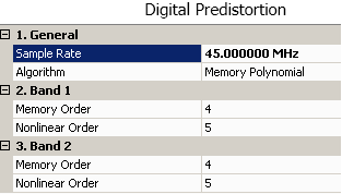
In the Digital Predistortion block set the switch to On.
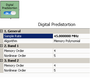
In the ![]() right panel, do the following:
right panel, do the following:
Set the Sample Rate to 45 MHz, which makes the oversampling ratio of both the waveforms to be 4. Both of the waveforms will be resampled to the sampling rate specified here. To extract the DPD model, it is expected that the oversampling ratio of both waveforms is no less than 3.
Set the Memory Order of Band 1 to 3, and set the Nonlinear Order of Band 1 to 4.
Set the Memory Order of Band 2 to 3, and set the Nonlinear Order of Band 2 to 4.
Different power amplifiers may have different characteristics, which will need different DPD models to simulate the DPD performance. In DPD test, if the measurement results are not as expected, you can try to change the parameters for DPD model extraction.
Click the RF Signal Generator block. In the right panel, do the following:
Enter the IP address or host name of the RF Signal Generator and the toggle the connect button on the top of the window to Connected state. After the instrument is connected, the model number and serial number of the instrument will be displayed in the Instrument cell.
Set Frequency to 2.5 GHz on RF Signal Generator 1, and set Frequency to 2.1 GHz on RF Signal Generator 2.
Click the PA block. In the right panel, do the following:
Enter the PA information by setting the Loss Out, Loss In, and PA Gain for both bands.
Set Input Power to -1 dBm for Band1 and -2 dBm for Band2.
The initial Amplitude setting in the RF Signal Generator block will be set to (Input Power + Loss In) automatically.
Click the Signal Analyzer block. In the right panel, do the following:
Enter the IP address or host name of the Signal Analyzer and the toggle the connect button on the top of the window to Connected state. After the instrument is connected, the model number and serial number of the instrument will be displayed in the Instrument cell.
Set the Capture Sample Length to 61440 samples. For most cases, you can use the default values in this model.
Click the  button to change the current view from
 ![]() block view to
block view to ![]() measurement view.
measurement view.
Click the Envelope Signal Generator block. In the ![]() right panel, do the following:
right panel, do the following:
Select the type of Envelope Signal Generator in the Configuration setting. In this example, select Arbitrary Waveform Generator.
Enter the IP address or host name of the Envelope Signal Generator and the toggle the connect button on the top of the window to Connected state. After the instrument is connected, the model number and serial number of the instrument will be displayed in the Instrument cell.

For other values, you can use the default settings. Note that the Voltage and Voltage Offset value will be set automatically after the test flow is run.
Refer to Voltage Mapping in Envelope Tracking Measurement for more details about Voltage Mapping.
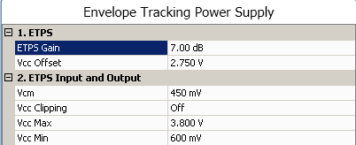
Click the ETPS block. In the ![]() right panel, do the following:
right panel, do the following:
Set the ETPS Gain to 7.0 dB.
Set the Vcc Offset to 2.75 V.
Set the Vcm to 450 mV.
Refer to Voltage Mapping in Envelope Tracking Measurement for more details about Voltage Mapping.
Switch the Envelope Tracking block to On. In the ![]() right panel, do the following:
right panel, do the following:
![]()
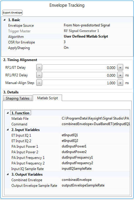
Select the From Non-predistorted Signal as the envelope source.
Select 2D Supply Modulation Technique as the algorithm which is internal algorithm.
Set OSR for Envelope to 3.
Regarding the timing alignment related setting, user can set the course value which can be used to later alignment action.
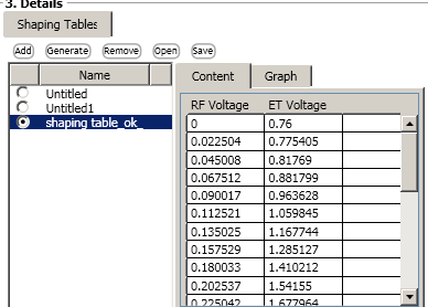
In the Details part, user add their own ![]() shaping table.
shaping table.
Set Algorithm to User Defined Matlab Script. Under Details, a Matlab Script ![]() property grid appears.
property grid appears.
This feature provides one interface for running a user-defined Matlab script file to generate the envelope waveform when the Envelope Source is from the IQ waveform, including Non-Predistorted Signal and Predistorted Signal.
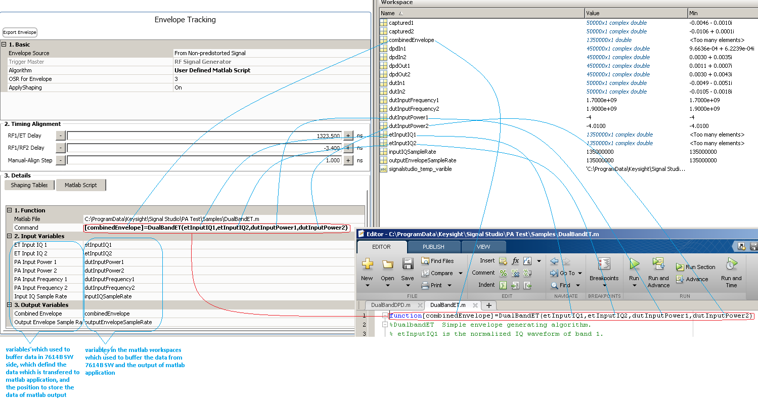
In the Matlab File field,navigate to the user-defined Matlab .m file you want to use. Notice that the Matlab function name is displayed in the Command field. The Command field also includes the values of ET Input IQ 1, ET Input IQ 2, PA Input Power 1, and PA Input Power 2, which must be contained , while other input parameters are optional. The Input Variables define the data buffer in the N7614C software. See ![]() table for descriptions.
table for descriptions.
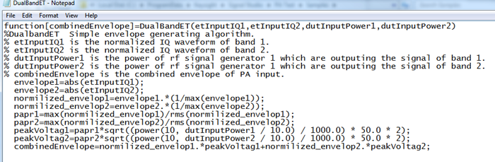
The software's installation directory provides a few sample Matlab files that you can use to get started, such as ![]() DualBandET.m.
DualBandET.m.
The Command field contains the variables that will be created in the Matlab workspace as the buffer and known by N7614C software. You must enter these variable names into the corresponding fields under Input Variables in the N7614C software. This ![]() diagram shows the mapping of variables between the N7614C software and Matlab.
diagram shows the mapping of variables between the N7614C software and Matlab.
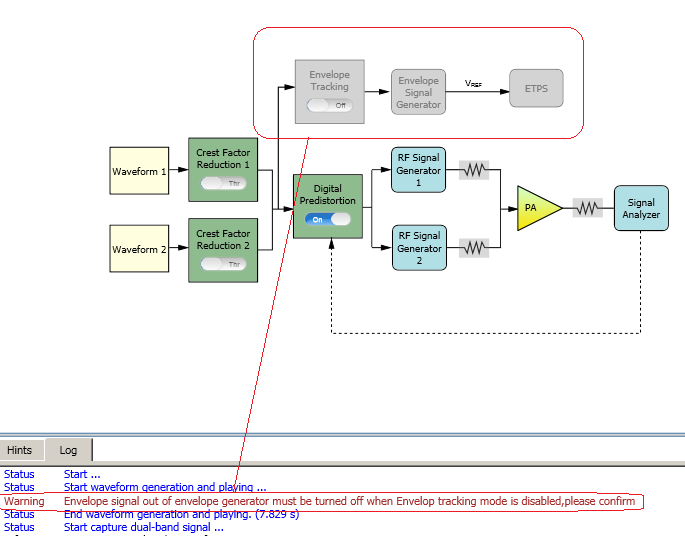
If ET-related hardware is in the system, make sure the envelope signal generator will not output signal to ETPS to maintain stable DC voltage at PA VBAT end. Otherwise, the DPD result will not be as good as expected. If envelope signal generator is online, the N7614C software will reset it automatically. Otherwise, you need to manually reset it. ![]() View image.
View image.