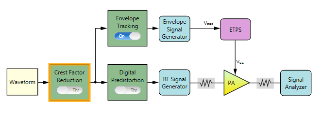
The following figure shows the block view settings in N7614C for ET measurement. In this example, the Digital Predistortion block is turned Through and Envelope Tracking block is turned On.
The remaining section of this topic provides an example procedure of setting N7614C for the envelope tracking measurement. Note that for different PA, the settings are different.
Step 1: Set the Waveform Block
Step 2: Set the Crest Factor Reduction Block
Step 3: Set the Envelope Tracking Block
Step 4: Set the Envelope Signal Generator Block
Step 7: Set the RF Signal Generator Block
Step 8: Set the Signal Analyzer Block
Step 9: Set the Measurement View
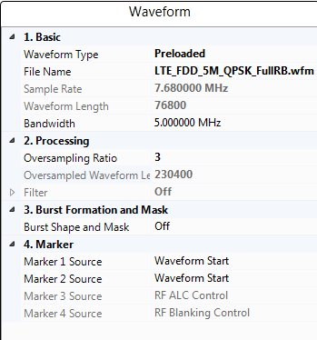
Click on the Waveform block icon on the UI. In the right panel, do the following:
Select Preloaded as the Waveform Type and select the "LTE_FDD_5M_QPSK_FullRB.wfm" file.
If you want to use a waveform generated by another Keysight signal studio, set Waveform Type to Signal Studio and select the file.
Note that to use a waveform generated by another signal studio software for ET test, the instrument needs to have the corresponding license. For this example, to use LTE waveform, the N7624B license needs to be installed in the instrument.
Set the bandwidth to 5 MHz according to the waveform bandwidth.
Set the Resampling Ratio to 3.

![]()
Set the Envelope Source to From Non-predistorted Signal. Then the software will calculate the envelope signal using the signal before Digital Predistortion block.
Set the Trigger Master to Envelope Signal Generator if the RF Signal Generator in use is N5172B or N5182B. Otherwise, set the Trigger Master to RF Signal Generator.
Set the OSR for Envelope to 3.
For signals used for envelope tracking test, it is recommend that the overall oversampling ratio (OSR) is no less than three. In this software, there are three different places related with the overall OSR. One is the OSR in the waveform file imported in the Waveform block. Another is the Resampling ratio setting in the Waveform block. The other is the OSR setting here in the Envelope Tracking block. The overall oversampling ratio is the product of these three values. As you increase the overall OSR, make sure the final sample rate does not exceed the limit of the Envelope Signal Generator.
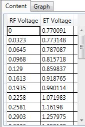
Set the Conversion Input Type to Absolute RF Output Voltage. This is to set the reference for the RF Voltage column in the shaping table.
Enter the shaping tables. This shaping table is used to map the selected Conversion Input Type, Normalized I/Q Amplitude, Absolute RF Output Voltage or Override Absolute RF, to the supply voltage of the PA (Vcc).
Here a shaping table is used as an example and you can see the graphic view by clicking the Graph tab.
Refer to Voltage Mapping in Envelope Tracking Measurement for more details about Voltage Mapping.
Click the Envelope Signal Generator block icon on the UI. In the right panel, do the following:
Select the type of Envelope Signal Generator in the Configuration setting. In this example, select MXG/EXG.

For other values, you can use the default settings. Note that the Voltage and Voltage Offset value will be set automatically after the test flow is run.
Refer to Voltage Mapping in Envelope Tracking Measurement for more details about Voltage Mapping.
Click the ETPS block icon on the UI. In the right panel, do the following:
Set the ETPS Gain to 7.0 dB.
Set the Vcc Offset to 2.75 V.
Set the Vcm to 450 mV.
Refer to Voltage Mapping in Envelope Tracking Measurement for more details about Voltage Mapping.
Click the PA block icon on the UI. In the right panel, do the following:
Enter the PA information by setting the Loss In, Loss Out, and PA Gain.
Select PA Input as the Power Mode.
Set Power to -5 dBm. This is to set the input power of the PA. Then the Amplitude setting in RF Signal Generator block will be set to (Power + Loss In) automatically.
Click the RF Signal Generator block icon on the UI. In the right panel, do the following:
Set Frequency to 2 GHz.
Click the Signal Analyzer block icon on the UI. In the right panel, do the following:
Note that the Frequency value is coupled to the frequency setting in RF Signal Generator block.
Set the Trigger Source to External 1 and adjust Trigger Delay value as needed. For most cases, you can use the default value.
 button on the
You can turn Intermediate Result to On and set the ACP parameters as required. In this example, the default settings are used.