The ET waveform can be generated from the input IQ waveform, which can be either non-predistorted waveform before the DPD block or predistorted waveform after the DPD block.
The IQ data is oversampled again and then the envelope |X| is calculated.
RF Voltage -> ET Voltage transformation is applied based on the input shaping table.
A user-defined ET waveform can also be used. In this case, most of the settings in ET and ETPS blocks are not applicable anymore.

Click this button to save the envelope data to a binary file.
The format of the exported envelope data is compliant with the format of the Envelope Signal Generator. See the "Truefrom Series Waveform Generators - Operating and Service Guide" for more details.
Choice: From Non-predistorted Signal | From Predistorted Signal | User Defined
Default: From Non-predistorted Signal
Coupling:
The Predistorted Signal option is not available if the Digital Predistortion block is turned through.
If the Envelope Source is set to User Defined, the software does NOT support any ET waveform shaping and generation any more. So in this case, the Shaping Tables is not available and the ETPS settings in ETPS block are grayed out. You need to ensure the Voltage and Voltage Offset settings in the Envelope Signal Generator block are correct.
The selection of this parameter determines the input signal of the Envelope Tracking block, thus changes the display of the block view.
Double-click or use the drop-down menu to specify the source of the envelope signal.
Choice: Big Endian | MATLAB
Default: Big Endian
Coupling: Available only when the Envelope Source is set to User Defined.
Set the type of the envelope file.
Coupling: Available only if the Envelope Source is set to User Defined.
Click the  in the right side of the cell to browse the computer and select the envelope signal file to use.
The supported format of the envelope file is compliant with the waveform format of the Envelope Signal Generator, which is the same as the format of the exported envelope file by pressing the Export Envelope button.
Choice: Envelope Signal Generator | RF Signal Generator
Default: Envelope Signal Generator
Coupling:
If Trigger Master is set to Envelope Signal Generator, the Trigger Source in the RF Signal Generator block will be set to External, the External Delay in the RF Signal Generator block will be set to On, and the Trigger Source in the Envelope Signal Generator block will be set to Bus.
If Trigger Master is set to RF Signal Generator, the Trigger Source in the RF Signal Generator block will be set to Bus, the External Delay in the RF Signal Generator block will be set to Off, and the Trigger Source in the Envelope Signal Generator block will be set to External.
Specify the relationship between the RF Signal Generator and Envelope Signal Generator.
Range: 1 to 32
Default: 3
Set the oversampling ratio for the envelope signal. The overall oversampling ratio should be the product of three OSR, including the OSR of the imported waveform, the Resampling Ratio setting in Waveform block, and the OSR for Envelope setting here.
The final sample rate should not exceed the limit of the Envelope Signal Generator in use.
Choice: Normalized IQ Magnitude | Absolute RF Output Voltage | Override Absolute RF
Default: Normalized IQ Magnitude
Specify the data type for the input of the shaping table. If the Override Absolute RF is selected, the Override Absolute RF Amplitude value is used for shaping table input calculate, instead of the real RF power setting of the RF Signal Generator.
Range: -144 to 30 dBm
Default: -10 dBm
Coupling: This parameter is visible only when Conversion Input Type is set to Override Absolute RF.
Set the absolute RMS power for use as the shaping table input.
Range: -20 s to 20 s
Default: 0
Set the delay of the envelope signal to the PA input signal. This value can be set by entering a value directly, or by pressing the  /
/ buttons.
Range: 1 ns to 100 ns
Default: 1 ns
Set the step of manual-alignment when you change the Delay setting using the / button. This value can be set by entering a value directly or by pressing the / button.
Select this check box to turn on Pre-Align for Auto-Align. This parameter is only used in Auto-Align process.
If the check box is selected, Auto-Align starts with a Pre-Align process, in which δEVM is measured using a pre-defined delay value. If the δEVM is smaller than 8%, Auto-Align will continue using ACP results. Otherwise, δEVM measurement will be repeated using another four delay values, centered by the pre-defined delay value. In this process, if the δEVM is smaller than 8%, Auto-Align will continue using ACP results. Otherwise, Auto-Align will quit with warning. Using Pre-Align helps finding a better initial delay value for Auto-Align, but it may take longer time.
If the check box is unselected, Auto-Align is performed using ACP results.
This section is used to configure the shaping tables. As shown in the following figure, there are four buttons on the top, Add, Remove, Open, and Save.
On the left is a list of the shaping tables, and on the right is the details for the selected shaping table including the content and graph.
For the shaping table, the first column "RF Voltage" stands for the amplitude of the envelope signal with the Conversion Input Type. The second column "ET Voltage" stands for the power supply of the PA (Vcc). For more details about voltage mapping, refer to Voltage Mapping in Envelope Tracking Measurement.
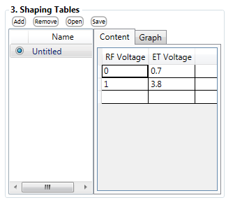

Click button to add a new shaping table. The new table is added to the end of the list.

To remove a shaping table, select the table name in the list, then click button.

Click button to import a shaping table.

Click button to save the table as .csv file.