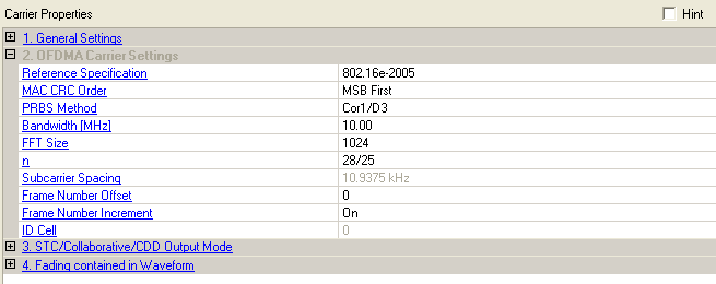

Choices: 802.16-2004 Cor1/D2, 802.16-2004 Cor1/D3, 802.16Rev2 (default)
This parameter is available with the advanced license.
Double-click or use the drop-down menu to select the reference specification to be used for waveform generation. The Reference Specification parameter is coupled to MAC CRC Order and PRBS Method as shown in the table below. When the Reference Specification is changed, the MAC CRC Order and PRBS Method change automatically. However, the MAC CRC Order and PRBS Method can be changed manually without affecting the Reference Specification.
|
Reference Specification |
MAC CRC Order |
PRBS Method |
|---|---|---|
|
802.16-2004 Cor1/D2 |
LSB First |
Cor1/D2 |
|
802.16-2004 Cor1/D3 |
LSB First |
Cor1/D3 |
|
802.16Rev2 |
MSB First |
Cor1/D3 |
: uses a different coding method for data randomization as described in section 8.4.9.1 of the standard.
: When this is selected, the CRC is calculated as described in section 6.3.3.5.2 of the standard, which states that the bits of each byte of the MAC PDU are sent to the CRC generator with the MSB first. Also, setting the bandwidth updates the value of the sampling factor (n) to comply with the coupling between these two parameters as described in section 8.3.2.3 of the standard:
For channel bandwidths that are a multiple of 1.75 MHz, n = 8/7
For channel bandwidths that are a multiple of 1.25, 1.5, 2, or 2.75 MHz, n = 28/25
For channel bandwidths not otherwise specified, n = 8/7
If the reference specification is changed from a different standard to 802.16Rev2, the sampling factor does not automatically update. The sampling factor is only checked and updated when the bandwidth setting is changed.
Choices: MSB First, LSB First
Double-click or use the drop-down menu to select the MAC CRC calculation order.
MSB First – the CRC is calculated as described in the standard (section 6.3.3.5.2), which states that the bits of each byte of the MAC PDU are sent to the CRC generator with the MSB first.
LSB First – the bits of each byte of the MAC PDU are sent to the CRC generator with the LSB first, which is used in Cor1/D2 and Cor1/D3.
This parameter is available with the advanced license.
Choices: Cor1/D2, Cor1/D3
Double-click or use the drop-down menu to select the data randomization method in section 8.4.9.1 of the standard.
This parameter is available with the advanced license.
Choices: 1.25, 3.50, 4.375, 5.00, 7.00, 8.75, 10.00 (default), 14.00, 15.00, 17.50, 20.00, 28.00
Double-click or use the drop-down menu to select the bandwidth of the generated OFDMA signal.
The software
checks that the selected bandwidth and frame duration combination are
compatible with the system profiles in the standard. If they do not match
a  standard profile,
a caution message is logged in the parameter status window.
If you are using reference specification 802.16Rev2,
when you select the bandwidth, the sampling factor, n, will automatically
be displayed as  specified
in section 8.4.2.3 of the 802.16Rev2 standard. You can change this value
manually, if desired. Selecting a new bandwidth associated with a different
value of n also updates the value of n.
Choices: 512, 1024 (default), 2048
Double-click or use the drop-down menu to select the FFT point size. The FFT size is independent of the selected bandwidth.
Choices: 8/7, 28/25 (default)
Double-click or use the drop-down menu to select the sampling factor for n (also referred to as Fs/BW) as allowed by the standard for your selected bandwidth. The parameter status window displays a caution message if the value does not match the standard for the chosen bandwidth.
If you are using reference specification 802.16Rev2,
when you select the bandwidth, the sampling factor, n, will automatically
be displayed as  specified
in 802.16Rev2 standard. You can change this value
manually, if desired. Selecting a new bandwidth associated with a different
value of n also updates the value of n.
Default: 10.9375 kHz
Displays the subcarrier spacing (ratio of the FFT size to channel width) that is automatically set by the software, depending on the bandwidth. This cell is read only.
Range: 0 to 16777215
Specify the frame number offset. This parameter is coupled with Built Frames.
For example, if Frame Number Offset = 5, and Build Frames = 16, a total of 16 frames from #5 to #20 are built.
In Uplink Only (FDD) mode, the UL-MAP allocation information won't be included in the signal. However, You can use Frame Number Offset to indicate the frame, where UL-MAP is located. This information is used to initialize PRBS (Cor2/D3).
Choices: On, Off
Double-click or use the drop-down menu to choose whether the frame number should increase for each frame during multi-frame waveform generation. You can also use this parameter to control whether the UL-MAP and DL-MAP are allocated in the same frame or allocated in the incremental frame during multi-frame waveform generation.
This parameter is available with the advanced license.
Range: 0–31
Displays the cell ID. This parameter updates to correspond with the preamble index that is set in the Downlink window. Refer to Table 459, 460 and 461 in the IEEE P802.16Rev2/D6 standard for related preamble index, ID cell, and segment index values.