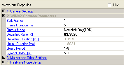

Enter the number of frames of the waveform to be built. The built frame range adjusts automatically depending on these selections. The frames all have the same configuration, but the frame number increments accordingly unless Frame Number Increment is turned off. Data patterns are continuous across the frames for each burst. This parameter is coupled with Frame Number Offset.
The maximum number of the built frames depends on the instrument arbitrary waveform memory. The whole waveform should not exceed the memory size of the instrument. You should check Total Sample Points to make sure it is less than the available memory size (not to exceed 64 Msamples).
Choices: 2 ms, 2.5 ms, 4 ms, 5 ms, 8 ms, 10 ms, 12.5 ms, 20 ms, Continuous
Double-click or use the drop-down menu to select one of frame
durations (ms) compatible with the selected bandwidth as allowed by
the standard. If they do not match a  standard
profile,
a caution message is logged in the parameter status window when you generate
the waveform. In continuous mode, both Downlink
Duration and Uplink
Duration are configurable. The default frame duration is 5 ms.
For 7 MHz BW, 5 ms is not an allowed frame duration according to the standard profiles listed in the online help, but the caution message is removed in the software because the WiMAX Forum specifies that combination as a system profile.
|
Frame Duration |
Output Mode |
Downlink Ratio |
Downlink Duration [ms], Uplink Duration [ms] |
|---|---|---|---|
|
2 to 20 ms
|
Downlink Only (TDD) Uplink Only (TDD) Both DL and UL (TDD) |
1 to 99% |
Automatically adjusted using the values in and |
|
Downlink Only (FDD) Uplink Only (FDD) |
N/A |
Automatically adjusted using the value in |
|
|
Continuous
|
Downlink Only (TDD) Uplink Only (TDD) Both DL and UL (TDD) |
N/A |
Manually set both and |
|
Downlink Only (FDD) Uplink Only (FDD) |
N/A |
Manually set either or |
Double-click or use the drop-down menu to select which parts of the signal are included in the generated waveform.
The frame plot view shows non-transmitted parts in a grayed out color. If a portion is not configured, a gap is shown in the frame for that period of time.
– only the downlink is included in the generated waveform. In this mode, you can configure an uplink to provide information for the UL-MAP and the UCD without having the uplink signal actually included in the waveform.
– the entire frame time is used for the downlink since the uplink is transmitted on a different frequency.
– only the uplink is included in the generated waveform. It starts at some delay from the frame start time based on the Downlink Ratio setting.
– the entire frame is used for the uplink. The uplink starts at the beginning of the frame.
– the waveform includes both the downlink and the uplink as configured.
the waveform includes two downlink subframes for Group 1 and Group 2 MS respectively.
- the waveform includes uplink signals from H-FDD MS in two groups.
Range: 1 to 99%
Set the percentage of the frame time to be used for the downlink, and
also set the start time for the uplink. The cell is only active when
the output mode is TDD and the frame duration is other than .
The frame plot viewshows a marker ( )
at the division point.
In FDD transmission, the selected link occupies the entire frame and the respective gaps are automatically adjusted to fill the frame.
Go to the Determining Downlink Ratio Values topic for details on how to set up the Downlink Ratio.
Range: 0 to 20 ms
Set the downlink duration in ms. This cell is configurable only when is set to .
Range: 0 to 20 ms
Set the uplink duration in ms. This cell is configurable only when is set to .
Choices: 1/4, 1/8, 1/16, 1/32
Default: 1/8
Double-click or use the drop-down menu to set the guard time.
Range: 0 to 10%
Set the windowing width to reduce the spectral
leakage and smooth out the transition from one symbol to the next. The
 windowing width
is specified as a percentage of one symbol.
Selecting a larger symbol rolloff value tends to improve ACPR but may make the EVM worse.