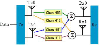
This example shows how to create waveforms for the 2x2 MIMO Matrix B system (as shown below) with two DL PUSC zones. It assumes that you know the frame structure, zones, and bursts that you want to set up, and is a "tops down” approach. Two bursts are created within the DL PUSC zone, each with a different modulation type for demonstration purposes. You might use this type of setup for receiver test.

In parameter configuration windows, you can check  in the upper right, and then click the desired
parameter for a brief description.
Set up the PC and the instruments as shown in Multiple Antennae Solution without Baseband Timing Alignment and RF Phase Coherency.
From the , select .
Click the two under in the tree view to set up the frequency and amplitude for the instruments. The setting should be the same for both of them. See Power Setting for more details.
Click n the tree view. This section of the table contains the key system parameters. These parameters include the number of frames to build in the waveform, the output mode, and downlink ratio. The default settings are used for this exercise.
Click in tree view.
: Use the default of 802.16e-2005 for this example. However, flexibility is provided to select either 802.16-2004/Cor1/D2 or 802.16-2004/Cor1/D3 depending on which standard specifications you want to use for subchannel randomization and subcarrier allocation.
: Use the default 10 MHz.
: Use the default 1024.
Click the frame tab in the lower portion of the window to display the
frame plot view.
A small yellow triangle
at the bottom of the graph indicates the division between the downlink
and uplink. The available subframe time determines how many symbols can
be put into the subframe (see  example.)
Note that when the output mode is Downlink Only (TDD), the RF burst off
time will include any unused frame time, shown as a gap (TTG), plus the
uplink portion (grayed out) of the TDD frame.
Click in the tree view. The lower half of this window allows you to add, delete, or copy PUSC, FUSC or AMC zones. Note that there are two PUSC zones under the downlink node by default.
You can delete an unwanted zone by clicking in the first column and then clicking Delete. However, Zone#1,PUSC is the default zone and cannot be deleted or re-ordered.
Click in the tree view. Note the additional zone view to the right of the frame plot. The Zone Setting window displayed in the parameter view lists parameters specific to this zone. Zone boosting is used to increase the power in the DL PUSC zone when not all subchannels are in use. The zone boosting factor is calculated by the software and cannot be changed. Use default values for this example.
: You can choose whether to automatically generate an FCH, DL-MAP, or UL-MAP which is always at the start of the first zone when present. Leave Auto FCH on and Auto UL-MAP off for this example. Turn on the Auto DL-MAP since a normal DL signal would contain a DL-MAP.
The bottom half of the screen allows you to add
bursts to this zone. One regular burst is present by default. Click  to add second regular burst. The white
fields in the table can be edited directly, while the gray fields cannot
be changed here (true in general for similar tables in this software).
Click in the tree view. Set the to Matrix B.
In keeping with the standard, the first DL-PUSC zone can not be set for STC.
Click in tree view.
Notice that the is 2 and the is 2, because you have chosen Matrix B as the STC type under the second PUSC zone.
:
Turn channel fading on if you want to create waveform that would be received by the receiver antennae. Then you can specify the fading channel parameters, which represent the condition between the combination of the two base station antennas and the two subscriber station antennas in a 2x2 MIMO configuration.
Turn channel fading off if you want to create waveforms that correspond to the transmitted signal from the two base station antennas.
Click  to verify all parameters are okay. View the result
in the window at the bottom
of the main window.
Click on in the tree view to view the CCDF, Waveform, or Power Envelope graphs at the bottom of the page if desired.
Click  to generate waveform.
Click  to download waveforms to the instruments if you have configured the instrument
connection.
When channel fading is off, the waveform for the transmitter antenna 0 will be downloaded to the master instrument and the waveform for the transmitter antenna 1 will be downloaded to the slave instrument.
When channel fading is on, the waveform for the receiver antenna 0 will be downloaded to the master instrument and the waveform for the receiver antenna 1 will be downloaded to the slave instrument.