Range: 0 to 31
Select the permutation base used for subchannel randomization in this zone. Refer to section 8.3.5.3.4, STC DL Zone IE format, section 8.3.9.4, Modulation, and section 8.3.6, OFDMA subcarrier allocation in P802.16Rev2/D6 for standard specifications.
Range: 0 to 3
Set the PRBS ID (0 to 3) in the zone used for subchannel randomization. Refer to section 8.3.5.3.4, STC DL Zone IE format, section 8.3.9.4, Modulation, and section 8.3.6, OFDMA subcarrier allocation in P802.16Rev2/D6 for standard specifications.
Range: 1 Bins by 6 Symbols, 2 Bins by 3 Symbols, 3 Bins by 2 Symbols, 2 Bins by 6 Symbols
Default: 2 Bins by 3 Symbols
Double-click or use the drop-down menu to set the AMC type.
2 Bins By 6 Symbols only used in STC mode.
Default: Off
Double-click or use the drop-down menu to turn Use All Subchannels On or Off.
On - all subchannels will be used for this zone.
Off - subchannels are assigned according to AMC Physical Bands Bitmap setup when it is enabled; otherwise all subchannels will be used.
According to P802.16Rev2/D6, this field in STC_DL_Zone_IE and UL_Zone_Switch_IE is ignored for AMC zones.
Double-click or use the drop-down menu to turn Zone Boost On or Off.
On: Adds gain to the used subchannels.
Off :The average power of a zone is lower.
Zone Boost is not available when Use All Subchannels is On.
Displays the zone boost amplitude in dB when zone boosting is enabled.
The values used in Zone Boost Factor and Power Boost are summed and applied to the zone when Zone Boost is On. For example, if the Zone Boost Factor is 3.01 dB, and Power Boost is 6 dB, then the final relative amplitude of the zone is 2.99 dB.
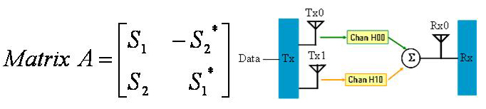
Double-click or use the drop-down menu to select the STC type, which decides whether this DL-AMC zone implements Matrix A, Matrix B or None STC encoding.
: Apply SISO signal effect for single antenna setup
: Also
known as Space-Time Code (STC). Transmit diversity is supported to provide
spatial diversity and reduce fading margin. For STC, the number of transmitter
antennas is 2 and the number of receiver antennas is equal to or greater
than 1.  View illustration.
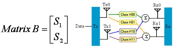
: Also
known as Spatial Multiplexing (SM) or MIMO. Multiple streams are transmitted
over multiple antennas to achieve higher throughput. For MIMO, the number
of transmitter antennas is equal to 2. The number of the receiver antennas
is equal to or larger than 2. View illustration.
Double-click or use the drop-down menu to select the MIMO DL IE Format.
: All the bursts are described in one single MIMO DL IE.
: Each burst is described in one separate MIMO DL IE.
: The bursts whose STC Type is the same with that of the zone are described in Normal burst IEs, while all the other bursts are described in one single MIMO DL IE.
: The bursts whose STC Type is the same with that of the zone are described in Normal burst IEs, while each of the other bursts are described in separate MIMO DL IEs.
MIMO DL IE Format is only available in STC mode.
Double-click or use the pull-down menu to set the use of dedicated pilots or full pilot transmission. When dedicated pilots are used, pilots are only transmitted for the subchannels that contain data.
Specify the number of symbols in this zone. Since the AMC type is 2 bins by 3 symbols (2x3), the number of symbols must be a multiple of 3.
Displays how much the zone is offset from the downlink preamble. It depends on the number of symbols used for any previously added zones.
This cell displays the maximum number of subchannels per symbol for this zone, based on the FFT size.
Select whether the bursts will be automatically generated (On) or manually allocated (Off). With auto allocation on, the software will configure the bursts based on the number of assigned slots and maximum number of subchannels available in the zone, avoiding any burst overlap where possible. Selecting auto allocation off activates the symbol and subchannel offsets in the burst editing window which can be edited for manual burst allocation.
Use this cell to automatically select (On) or manually select (Off) how the bursts will be allocated in the zone. Selecting off enables you to edit the symbol and subchannel offsets and the assigned slots cells in the burst editing window.
Use the Add Button  to add a new burst. When a burst is added, the software
displays the burst in the tree view and adds it to the frame plot view.
to add a new burst. When a burst is added, the software
displays the burst in the tree view and adds it to the frame plot view.
Use the Delete Button  to delete the selected burst. The burst to
be deleted is indicated by the
to delete the selected burst. The burst to
be deleted is indicated by the ![]() in the first column.
in the first column.
Use the Copy Button  to add a new burst that has the same configuration
as the currently selected one (indicated by the
to add a new burst that has the same configuration
as the currently selected one (indicated by the ![]() in the first column).
in the first column).
Use the Up and Down arrows  to reposition the currently selected burst
(indicated by the
to reposition the currently selected burst
(indicated by the ![]() in the first column).
in the first column).
Range: 1 to 16
Displays the burst index number.
Displays the type for the burst.
Regular bust- non-HARQ scheme enabled burst.
HARQ burst (Hybrid ARQ)- HARQ scheme enabled burst.
Chase Combining
IR CTC HARQ
IR CC HARQ
Use the drop-down menu to select a STC Type. See STC Type for details.
Use the pull down menu to select a modulation and coding type. See also Modulation and Coding.
Choices: None, 2, 4, 6
Use the pull-down menu to select the number of times the data is repeated. See also Repetition Coding.
Displays the number of symbols assigned for this burst. See also Number of Symbols.
Displays the symbol offset of the burst. See also Symbol Offset.
Displays the number of subchannels assigned for the burst. See also Number of Subchannels.
Displays the subchannel offset for the burst. See also Subchannel Offset.
Choices: None, SUB-DL-UL-MAP #1, SUB-DL-UL-MAP #2, SUB-DL-UL-MAP #3
Use the drop-down menu to select the MAP message where the IE for this burst is located.
'None' means that the burst IE goes into normal or compressed MAP message.