This example shows you how to set up the equipment and configure the N7617C Signal Studio for WLAN 2026 Update 1.0 software to create 802.11n waveform packets for a Mx2 (2-antenna receiver) MIMO receiver test application without baseband timing alignment and common local oscillator. Although this example demonstrates Mx2 MIMO, it is easy to expand it to Mx3 and Mx4 MIMO by adding extra signal generators, connecting the corresponding cables, and configuring the Signal Studio software.
In this example, two E4438C signal generators (with the same model number) are used and the 10 MHz references are connected between them.
The Event 2 connector on the primary signal generator is connected to the Pattern Trigger In connector on each of the two signal generators. It synchronizes the start of the waveforms playback on both signal generators. The synchronization occurs right after the software downloading the waveforms to the both signal generator. The Signal Studio software will send a SCPI command to the primary signal generator to direct it to send a one-time event pulse through the Event 2 connector to itself and the secondary signal generator. Then, this pulse signal triggers the two signal generator to playback the waveform with synchronization. Note that there is still an error of one cycle of the baseband generator clock between the primary and the secondary. Each signal generator only recognizes the pattern trigger input the next time that the BBG clock signal has a rising edge, and since the two BBG clocks are not phase matched, the rising edge can occur as much as one clock cycle apart on the two signal generator. To achieve the baseband timing alignment, use the setup in Multiple Signal Generators Solution with Baseband Timing Alignment, but without RF Phase Coherence topic.
The EVENT 2 signal works as both a Trigger Source and an actual Marker 2 output signal, but in different period of time. Before the waveform playback, EVENT 2 serves as the trigger source. Once waveforms are triggered to playback, EVENT 2 won't work as a trigger source and come back to the Marker 2 output whenever marker 2 is present in the waveform.
When you start the N7617C Signal Studio for WLAN 2026 Update 1.0, you will need to choose the in the System Configuration Wizard. You will be asked for connection information for the corresponding number of signal generators. Both signal generators must be the same model and both must have a valid license for N7617C Advanced Capability in order to have access to most of the software features for MIMO.
The N7617C Signal Studio for WLAN 2026 Update 1.0 software pre-calculates the waveform packets and applies the effects of specific channels, then loads the composite waveform into each signal generator and applies it directly to the DUT's receiver inputs. You might use this type of setup for MIMO Mx2 receiver test.
Set up the PC and the signal generators as shown above.
Click the button in the tree view and double click the IEEE 802.11n Mx2 in the right pane to open the parameter view main window. If you want to expand your setup to Mx3 or Mx4 MIMO, select IEEE 802.11n Mx3 or IEEE 802.11n Mx4 respectively.
Click in the tree view to configure waveform parameters. The section contains the key system parameters.
: Select for this example.
: Select for this example.
: Use the default setting, . This parameter determines the length of the idle time between frames.
: Use the default .
Leave the default settings for the other parameters.
Click in the tree view to configure the parameters for the 802.11n PHY and MAC layer.
Configure parameters.
The can be changed if desired. It determines the number of spatial streams and the modulation type, coding rate, and data rate as shown in the MCS table. Since we have chosen IEEE 802.11n Mx2 in the quick setup, the range of possible choices for the MCS index is 0 to 15. Use any of these values.
set it to . This parameter determines the M value in a MxNMIMO system. Since we have chosen Mx2 MIMO in the Quick Setups, setting this parameter to 2 means that we are configuring a 2x2 MIMO system.
Use the default of .
Use the default value of .
Set it to . This sets the guard interval to 800ns.
Set to . In GreenField mode, HT packets are transmitted without a legacy compatible part.
Use the scheme.
, , and : Enable scrambler, convolutional coder, and interleaver so that the channel is fully coded.
Configure data.
You can turn A-MPDU on or off. For this example, turn it on to allow multiple MPDUs in one PSDU (PHY service data unit).
The bottom half of the screen allows you to add MPDUs to this zone. One MPDU is present by default. Click to add a second one.
set it to .
Click in the tree view or double-click in the first column of the row in the table. This displays a window where you can choose the following for each MPDU.
: Select PN9 sequence.
: Use the default setting, 1024 bytes in this example.
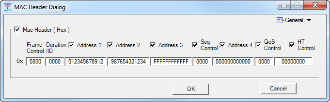
: MAC Header format is very important for receiver test. The MAC header provides the DUT with information about the data being transmitted. If the header is formatted incorrectly, the DUT will not recognize the frame, preventing FER/PER testing. It is critical that the frame control in the MAC header be set properly to obtain valid packets. IEEE 802.11, 1999, paragraph 7, Frame formats defines several frame types. To set the frame for data, the MAC header would be formatted to 0800. The second portion of the MAC header specifies addresses. Not all frame types use all the address fields. Signal Studio provides a checkbox that can be cleared if that is desired. Note that the frame length changes when the addresses are not selected. If the address of the DUT is not the same as that being transmitted, the frame will be ignored by the DUT, unless the device is in ad hoc mode. In this example, the MAC header for a data frame with addresses is set as shown in the figure below.
: Enable MAC FCS to append the MAC FCS to the data payload in this example.
Leave the default settings for the other parameters.
Configure by clicking in the tree view. Set to in this example for a Mx2 MIMO receiver test. (For a transmitter test application, set the channel state to OFF.)
Click the  button in the
cell to configure channel fading parameters.
button in the
cell to configure channel fading parameters.
: Use mode B in this example. Options A to F of model type correspond to channel models defined in IEEE 802.11-03/940r (IEEE p802.11 Wireless WLANs TGn channel models).
: Use the default in this example. You may also set it to Rice, depending on your test requirements.
: In this example, set it to so that the antenna correlations are computed from the signal voltages (complex).
: Displays the number of transmit antennae. It is equal to the number of transmit chains in HT mode in this example.
: Displays the number of receive antennae. It is determined by the number of signal generators you select in the quick setup. In this example, it is 2.
Leave the default settings for the other parameters.
Keep the default signal generator settings for the two signal generators.
Click  to view the CCDF
curves, if desired.
to view the CCDF
curves, if desired.
Click  to generate waveform packets.
Click  to download waveforms to each signal generator after you have configured
the instrument connection.
to download waveforms to each signal generator after you have configured
the instrument connection.