Ensure the equipment is turned off.
Connect the equipment to a computer using one of the following methods for instrument control:
-
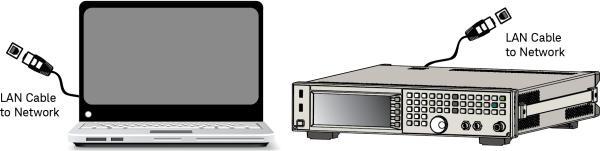
LAN Network—
 connect
the hardware and computer to an
external LAN network using standard LAN cables.
connect
the hardware and computer to an
external LAN network using standard LAN cables. If you are connecting to an E6640A, the instrument has two (2) LAN ports on the front panel. LAN 2 (the left most port) uses a static assigned IP address, and you should use the LAN 2 port to connect the test set.
-
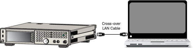
Crossover LAN—
connect
the hardware directly to the computer using a crossover LAN cable.
(You will need to configure your PC using this setup.)If you are connecting to an E6640A, the instrument has two (2) LAN ports on the front panel. LAN 2 (the left most port) uses a static assigned IP address, and you should use the LAN 2 port to connect the test set.
-
Crossover LAN—If
connecting
more than one instrument (signal generator, spectrum analyzer):-
one 10Base-T crossover cable for the PC
-
one 10Base-T cable for each instrument
-
one 10Base-T hub
-
-
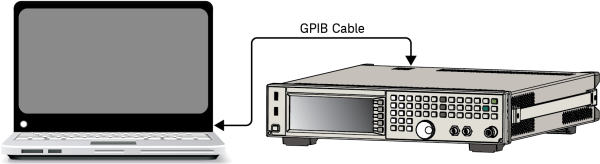
GPIB—
connect
the equipment directly to the computer
using a GPIB cable. -
PXI—connect the computer's MXI/PXI adapter to the PXI mainframe.