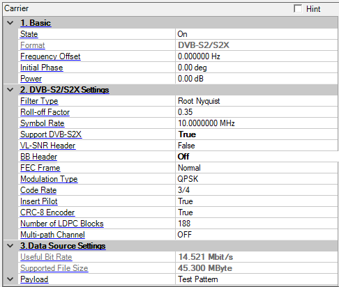
DVB-S2/S2X (EN 302307) is introduced to improve the transmission capability in the same bandwidth as DVB-S. More complicated BCH and LDPC coding and high order modulation scheme such as QPSK, 8PSK, 16APSK and 32APSK are adopted.
Choice: On |Off
Default: On
Double-click or use the drop-down menu to control the operating state of the carrier.
The format of the carrier.
Range: -40.0 to 40.0 MHz
Default: 0.000000 Hz
Set the frequency offset for the carrier relative to the signal generator’s frequency setting. The valid range will be different for every format due to the different over-sampling ratios.
For example, for 2 carriers configuration, set the center frequency of signal generator to 1 GHz, and make the two carriers distributed on the both sides of the center frequency with 5 MHz offset each. Therefore, the actual frequency of each carrier would be 1GHz+5MHz and 1GHz-5MHz respectively.
Range: 0 to 359 degrees
Set the initial phase of the carrier.
Range: -50 to 0 dB
Set the carrier’s power relative to the signal generator’s amplitude setting.
Choice: Nyquist \Root Nyquist
Default: Root Nyquist
Double-click or use the drop-down menu to select the filter type.
Conventionally, a data transmission system employs a Nyquist filter whose reply for an impulse is zero (0) for every interval T just before and after a peak (T: data transmission interval). As replies of adjacent data are zero on a sample point of other sampled data, interference between codes can be prevented.
To function as above, a Nyquist filter whose amplitude becomes half at the point where Nyquist frequency fN (=1/2T) is used, and it is odd-symmetrically rolled off with a squared cosine around the half amplitude point in the cutoff area. In this case the phase characteristics is not considered, or is designed to have linear phase characteristics usually.
Instead of a simple Nyquist filter, low-pass filters (root Nyquist filters) having equal amplitude are set for transmission and reception and their characteristics are made the same as that of the Nyquist filter above. In this case, the root Nyquist filter must have cosine characteristics that can be made the squared cosine characteristics above.
Range: 0 to 1
Default: 0.35
Set the roll-off factor of DVB-S2/S2X.
DVB-S2/S2X have taken into consideration of various requirements of multiple service. For one thing, it supports a wide range of code rates (from 1/4 up to 9/10); for another, roll-off factor can be selected among 0.35, 0.25, 0.2, instead of the fixed 0.35 in DVB-S. With lower roll-off factor, higher spectrum efficiency can be achieved.
Range: 300KHz to 100MHz
Default: 10MHz
Set the symbol rate of DVB-S2/S2X.
The symbol rate is matched to given transponder characteristics, since DVB-S.2 is suitable for use on different satellite transponder bandwidths and frequency bands, and in the case of multiple carriers per transponder (FDM), to the frequency plan adopted.
Choice: True | False
Default: False
Coupling: VL-SNR Header, FEC Frame, Modulation Type and Code Rate
Double-click or use the drop-down menu to select whether to support DVB-S2X.
Choice: True | False
Default: False
Coupling: FEC Frame, Modulation Type and Code Rate. VL-SNR Header can only be activated in DVB S2X
Double-click or use the drop-down menu to select whether to insert VL-SNR Header in PLFRAME in DVB-S2X.
Choice: On | Off
Default: On
Double-click or use the drop-down menu select whether to transmit BBHEADER in BBFRAME.
Choice: Normal | Medium | Short
Default: Normal
Coupling: Modulation Type, Code Rate and Number of LDPC Blocks
Double-click or use the drop-down menu to select whether to use normal, medium or short LDPC block size in DVB-S2/S2X.
FEC encoding performs outer coding (BCH), Inner Coding (LDPC) and Bit interleaving. The input stream is composed of BBFRAMEs and the output stream of FECFRAMEs. Each BBFRAME (Kbch bits) shall be processed by the FEC coding subsystem, to generate a FECFRAME (nldpc bits). The parity check bits (BCHFEC) of the systematic BCH outer code shall be appended after the BBFRAME, and the parity check bits (LDPCFEC) of the inner LDPC encoder shall be appended after the BCHFEC field, as shown below.
![]()
Figure 2 FEC Encoding Data Structure
LDPC encoding provides two kinds of frame length, one is normal frame with length 64800 bit; the other is short frame with length 16200 bit (1/4 of normal frame), shown in the following figure.
Table 1 FECFRAME (normal and short) configurations and application areas
|
System Configuration |
Broadcast Services |
Interactive services |
DSNG |
Professional Services |
|
|---|---|---|---|---|---|
|
FECFRAME(normal) |
64800 (bits) |
N |
N |
N |
N |
|
FECFRAME(short) |
16200 (bits) |
NA |
N |
O |
N |
|
N = normative, O = optional, NA = not applicable. |
|||||
Choice: BPSK | BPSK-S | QPSK | 8PSK | 8APSK | 16 APSK | 32 APSK | 64 APSK | 128 APSK | 256 APSK
Default: QPSK
Coupling: Code Rate
Double-click or use the drop-down menu to select the modulation type.
Choice: 1/5 | 1/4 | 1/3 | 2/5 | 1/2 | 3/5 | 3/5-L | 2/3 | 2/3-L | 3/4 | 4/5 | 5/6 | 2/9 | 7/9 | 8/9 | 9/10 | 11/45 | 13/45 | 9/20 | 11/20 | 4/15 | 8/15 | 11/15 | 5/9 | 26/45 | 28/45 | 29/45 | 31/45 | 32/45 | 23/36 | 25/36 | 13/18 | 77/90
Default: 3/4
Coupling: determines the value of Useful Bit Rate and Supported File Size
Double-click or use the drop-down menu to select the LDPC code rate of DVB-S2/S2X.
Choice: True | false
Default: True
Double-click or use the drop-down menu to select whether to insert pilot at the physical layer in DVB-S2/S2X. For the VL-SNR mode, Insert Pilot is always True.
When Insert Pilot is enabled, a PILOT BLOCK composed of P = 36 pilot symbols will be inserted. Each pilot shall be an un-modulated symbol, identified by I = (1/√2), Q = (1/√2). The first PILOT BLOCK shall be inserted 16 SLOTs after the PLHEADER, the second after 32 SLOTs and so on, as represented in figure 13. If the PILOT BLOCK position coincides with the beginning of the next SOF, then the PILOT BLOCK is not transmitted. Besides, the pilot presence/absence in VCM (Variable Coding and Modulation) and ACM (Adaptive Coding and Modulation) can be changed on a frame-by-frame basis.
Choice: True | False
Default: True
Double-click or use the drop-down menu to select whether to use CRC-8 before channal coding in DVB-S2/S2X.
Range: 188, 2*188, 3*188...
Default: 188
Select the number of LDPC blocks to be generated.
This is read only when Data Source Type is not Test Pattern.
Range: 0 to 262141
Default: 0
Sets or gets the Gold Sequence Index for PL Scrambling.
Default: OFF
Click
 in the right side of the cell to open the
 ![]() Multi-path Channel
configuration window.
Multi-path Channel
configuration window.
A multi-path channel which contains up to 20 paths can be set according to your test requirements.
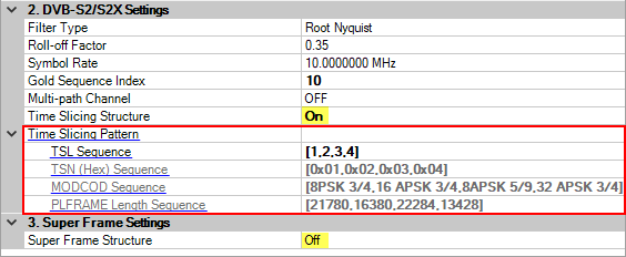
Choice: On | Off
Default: Off
Double-click or use the drop-down menu to select whether to use time slicing structure defined in Annex M in ETSI EN 302 307-1.
For more information, see Time Slicing Structure in Tutorials.
See also, DVB-S2/S2X TSL Configuration.
Sets or gets the time slicing pattern to configure the permutation of TSLs. When number of TSLs is more than one, this can be an array. The array is surrounded by "[" and "]", and the elements are separated by ",". The number of LDPC blocks can be calculated by the size of "Time Slicing Pattern" array.
Gets the TSN Sequence pattern for each TSLs.
Gets the MODCOD Sequence pattern for each TSLs.
Gets the PLFRAME Length Sequence pattern for each TSLs.
Choice: On | Off
Default: Off
Double-click or use the drop-down menu to select whether to use super frame structure defined in Annex E in ETSI EN 302 307-2.
For more information, see Super Frame Structure in Tutorials.
Choice: Format 5 | Format 4 | Format 6
Default: Format 5
Double-click or use the drop-down menu to select the format of super frame structure. Only format 5 is supported in the first version.
Range: 1 to 100
Default: 1
Sets or gets the number of super frames blocks to be generated.
Sets or gets whether to add SF-pilot. This is editable but double clicking and drop-down menu can’t be used. When number of super frames is more than one, this can be an array. The array is surrounded by “[“ and “]”, and the elements are separated by “,”.
The length of postamble sequence. This is the “L” value defined in E3.7.8. This is read-only and defined by the highest protection level in the dwell.
The length of postamble filled by (1+1j)/sqrt(2). When number of super frames is more than one, this can be an array. The array is surrounded by “[” and “]”, and the elements are separated by “,”. 0 means this super frame is not the last frame in the dwell and there is no postamble in this super frame.
Sets or gets the number of “capacity unit" (CU) in each super frame. When number of super frames is more than one, this can be an array. The array is surrounded by “[“ and “]”, and the elements are separated by “,”.
Gets the number of symbols in each super frame. This is SFL in Annex E. This is read-only and calculated by “Number of CU in Super Frame”, “Pilot”, “Postamble Sequence Length” and “Postamble Switching Length”.
Sets or get number of physical layer frames in each super frame. When number of super frames is more than one, this can be an array. The array is surrounded by “[“ and “]”, and the elements are separated by “,”.
Range: 0 to SFL
Default: 0
Sets or gets fragmentation in the first super frame. The unit is CU.
Choice: Off | On
Default: Off
Sets or get whether to reset data input for different cells for multi-cell cases. If off, the input bit stream is continuous from cell to cell. If on, the input stream is reset from cell to cell.
Sets or get the cell destination in each super frame. When number of super frames is more than one, this can be an array. The array is surrounded by “[“ and “]”, and the elements are separated by “,”. When the super frame doesn’t have enough symbols for physical layer data, the remining physical data will be transmitted in the following super frame with the same cell destination as fragmentation.
Gets the pointer to the first complete PLH (counting in CU). This is read-only and defined by fragmentation and other super frame / physical frame settings. When number of super frames is more than one, this will be an array.
Gets the overflow length for each superframe. The Overflow of the last SF of the Cell is actually discarded.
Choice: Off | On
Default: Off
Sets or gets whether the baseband scrambling will be used before FEC. The BB scrambling is defined in 5.2.2 in ETSI EN 302 307-1.
Choice: PL00 | PL01 | PL10 | PL11
Default: PL00
Sets or gets the PLH protect level. This is editable but double clicking and drop-down menu can’t be used. When number of super frames is more than one, this can be an array. The array is surrounded by “[“ and “]”, and the elements are separated by “,”.
Choice: Off | On
Default: On
Sets or gets whether the two-way scrambling will be used. Tow-way scrambling is defined in defined in E2.4.
Sets or gets the golden code sequence index for reference data. When number of super frames is more than one, this can be an array. The array is surrounded by “[“ and “]”, and the elements are separated by “,”.
Sets or gets the golden code sequence index for payload data. When number of super frames is more than one, this can be an array. The array is surrounded by “[“ and “]”, and the elements are separated by “,”.
Sets or gets the row index for Start of Super-Frame (SOSF) field. When number of super frames is more than one, this can be an array. The array is surrounded by “[“ and “]”, and the elements are separated by “,”.
Sets or gets the row index for SF-Pilot field. When number of super frames is more than one, this can be an array. The array is surrounded by “[“ and “]”, and the elements are separated by “,”.
Sets or gets the PLS value for each physical frame. When number of physical frames is more than one, this can be an array. The array is surrounded by “[“ and “]”, and the elements are separated by “,”. The number of physical layer frames can be calculated by summing up the values in “Number of PL Frames in Each Super Frame” array.
Gets the modulation type for each physical frame.
Gets the LDPC code rate for each physical frame.
Gets the FEC frame type for each physical frame.
Gets the spreading value for each physical frame.
Sets or gets the TSN value for each physical frame. When number of physical frames is more than one, this can be an array. The array is surrounded by “[“ and “]”, and the elements are separated by “,”. The number of physical layer frames can be calculated by summing up the values in “Number of PL Frames in Each Super Frame” array.
Choice: 00 | 01 | 10 | 11
Default: 00
Sets or gets the last two bits in PLH. When number of super frames is more than one, this can be an array. The array is surrounded by “[“ and “]”, and the elements are separated by “,”
Gets the length for each physical layer frame in TSL. This is read-only and calculated by PLS.
The useful bit rate. The bit rate is determined by current bandwidth, encoding, modulation and framing configurations.
The supported file size for current settings.
The TS payload settings.
Choice: Test Pattern | Demo File | TS File | TS File Wizard
Default: Test Pattern
Double-click or use the drop-down menu to select which type to be used as the data source.
If "TS File" is selected, "File Name" is required; If "TS File Wizard" is selected, "File Wizard" is available.
Learn more about the different Data Source Types, refer to the page Data Source Type.
The data bits used as test pattern.
Click the right button to open the ![]() Data Pattern Selection dialog and select a test pattern to use.
Data Pattern Selection dialog and select a test pattern to use.
Choice: True | False
Default: False
Double-click or use the drop-down menu to determine whether a SYNC byte (0x47) should be inserted into the test pattern.
Choice: NTSC | PAL | HD 1920x1080
Default: PAL
Double-click or use the drop-down menu to select whether the PAL, NTSC or HD 1920x1080 file is demo File. This cell is only enabled when Data Source Type is Demo File.
In DVB-S2/S2X, we provide both SDTV (Standard Definition Television) and HDTV (High Definition Television).
HD 1920x1080 is a choice for HDTV.
There are two predominant worldwide video-based source material formats (SDTV), shown as follows:
NTSC: National Television System Committee, the system used in America & Canada
PAL: Phase Alternating Line, the system used in Western Europe and Australia
Table 2 NTSC parameters list
|
N T S C National Television System Committee |
|
|
Lines/Field |
525/60 |
|
Horizontal Frequency |
15.734 kHz |
|
Vertical Frequency |
60 Hz |
|
Color Sub-carrier Frequency |
3.579545 MHz |
|
Video Bandwidth |
4.2 MHz |
|
Sound Carrier |
4.5 MHz |
Table 3 PAL parameters list
|
P A L Phase Alternating Line |
|||
|
SYSTEM PAL |
PAL |
PAL N |
PAL M |
|
Line/Field |
625/50 |
625/50 |
525/60 |
|
Horizontal Freq. |
15.625 kHz |
15.625 kHz |
15.750 kHz |
|
Vertical Freq. |
50 Hz |
50 Hz |
60 Hz |
|
Color Sub Carrier |
4.433618 MHz |
3.582056 MHz |
3.575611 MHz |
|
Video Bandwidth |
5.0 MHz |
4.2 MHz |
4.2 MHz |
|
Sound Carrier |
5.5 MHz |
4.5 MHz |
4.5 MHz |
Click
on
in the right side of the cell, and select the file name you set as payload.
The name of the TS file as data source.
Click the right button to select and open a TS file.
If DVB-T/H, DVB-C, DVB-S, ISDB-T "RS Encoder" is off or ISDB-T "Re-Multiplexer" is off, a TS file with 204 byte packets is required;
If ATSC "RS Encoder" is off, TS file with 208 byte packets is required.
For the other situation, TS file with 188 byte packets is required.
Choice: ON | OFF
Default: ON
This cell is only enabled when Data Source Type is TS File. Double-click or use the drop-down menu to select whether or not to use auto-stuffing to agree with transport bit rate.
Choice: ON | OFF
Default: ON
This cell is only enabled when Data Source Type is TS File. Double-click or use the drop-down menu to determine whether or not to modify the TS file to make it suitable for loop play.