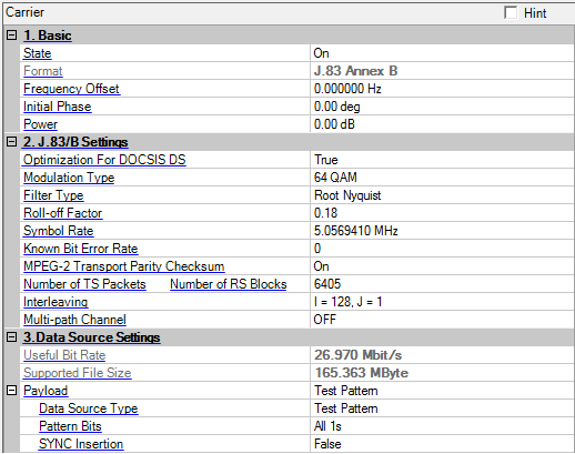
J.83 Annex B, applied for a digital multi-service television distribution system submitted to the ITU-T specific to a cable channel and based upon testing and characterization of cable systems in North America, can be used transparently with the distribution from a satellite channel, as many cable systems are fed directly from satellite links. The specification covers both 64 QAM and 256 QAM.


Choice: On |Off
Default: On
Double-click or use the drop-down menu to control the operating state of the carrier.
The format of the carrier.
Range: -40.0 to 40.0 MHz
Default: 0.000000 Hz
Set the frequency offset for the carrier relative to the signal generator’s frequency setting. The valid range will be different for every format due to the different over-sampling ratios.
For example, for 2 carriers configuration, set the center frequency of signal generator to 1 GHz, and make the two carriers distributed on the both sides of the center frequency with 5 MHz offset each. Therefore, the actual frequency of each carrier would be 1GHz+5MHz and 1GHz-5MHz respectively.
Range: 0 to 359 degrees
Set the initial phase of the carrier.
Range: -50 to 0 dB
Set the carrier’s power relative to the signal generator’s amplitude setting.
Choice: True | False
Default: True
Double-click or use the drop-down menu to enable or disable the optimization for DOCSIS DS.
Choice: 64QAM |256 QAM
Default: 64QAM
Select the Modulation type of the carrier.
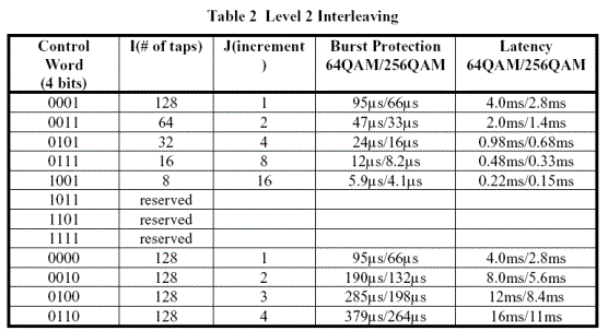
J.83 Annex B provides two distinct operating modes of interleaving capability are specified, called level 1 and level 2. Level 1 is specified for 64-QAM transmission only while Level 2 encompasses 64-QAM and 256-QAM transmission, and for both modulation schemes is capable of supporting variable interleaving.
Choice: Nyquist \Root Nyquist
Default: Root Nyquist
Double-click or use the drop-down menu to select the filter type.
Conventionally, a data transmission system employs a Nyquist filter whose reply for an impulse is zero (0) for every interval T just before and after a peak (T: data transmission interval). As replies of adjacent data are zero on a sample point of other sampled data, interference between codes can be prevented.
To function as above, a Nyquist filter whose amplitude becomes half at the point where Nyquist frequency fN (=1/2T) is used, and it is odd-symmetrically rolled off with a squared cosine around the half amplitude point in the cutoff area. In this case the phase characteristics is not considered, or is designed to have linear phase characteristics usually.
Instead of a simple Nyquist filter, low-pass filters (root Nyquist filters) having equal amplitude are set for transmission and reception and their characteristics are made the same as that of the Nyquist filter above. In this case, the root Nyquist filter must have cosine characteristics that can be made the squared cosine characteristics above.
Range: 0 to 1
Default: 0.18
Set the roll-off factor of J.83 Annex B.
Range: 300 KHz to 10MHz
Default: 5.0569410 MHz
Set the symbol rate of J.83 Annex B.
Range: upper limit is 1E-4, lower limit depends on frame length.
Default: 0
Set the known bit error rate of J.83 Annex B after RS. The error bits are added after RS coding. Caution: Because of RS and differential encoding, the TS packages should set to be multiple of 6405*4 (recommend 25620), data source should be test pattern of ”r;all ones”, ”r;all zeros”, ”r;PN9”, ”r;PN15”. Otherwise, there may be some unexpected error bit when the frame loops.
Choices:On | Off
Default: On
Set whether to use MPEG-2 Trasport Parity Checksum. When this is false, 188-byte TS package boundary is ignored so shorter waveform is supported.
Range: depends on modulation type and instrument memory size limitation
Default: 6405
The number of TS Packets in J.83 Annex B. Number of TS Packets will be coupled to a valid value based on current modulation type. Number of TS Packets is calculated when Data Source Type is Demo File, TS File and TS File Wizard.
Range: 210 to 160000
Default: 210
The number of RS Blocks in J.83 Annex B. Number of RS Blocks is valid when MPEG-2 Transport Parity Checksum is Off.
Choice: I = 128, J = 1 I = 128, J = 2| I = 64, J = 2| I = 128, J = 3 | I = 32, J = 4 | I = 128, J = 4 | I = 16, J = 8 | I = 128, J = 5 | I = 8, J = 16 | I = 128, J = 6 | I = 128, J = 7 | I = 128, J = 8
Default: I = 128, J = 1
Interleaving is included in the model between the R-S block coding and the randomizer to enable the correction of burst noise induced errors. In both 64-QAM and 256-QAM a convolutional interleaver is employed, which consists of a single fixed structure for the nominal 64-QAM (level 1), and a programmable structure for both 64-QAM and 256-QAM (level 2). The I and J interleaving parameters means '# of taps' and 'increment' separately.
Two distinct operating modes are provided regarding to the interleaving capability, that is level 1 and level 2.
Level 1 is specified for 64-QAM transmission only. This mode accommodates the installed base of legacy 64-QAM-only digital set tops. While operating in level 1, a single interleaving depth will be supported; namely I=128, J=1.
Level 2 shall encompass 64-QAM and 256-QAM transmission, and will for both modulation schemes be capable of supporting variable interleaving. This will include both enlarged and reduced interleaving depths relative to the nominal 64-QAM (level 1) configuration. Four data bits are transmitted in-band during the FEC frame sync interval to convey the interleaving parameters to the receiver for a given channel.


Default: OFF
Click
in the right side of the cell to open the
![]() Multi-path Channel
configuration window.
Multi-path Channel
configuration window.
A multi-path channel which contains up to 20 paths can be set according to your test requirements.
The useful bit rate. The bit rate is determined by current bandwidth, encoding, modulation and framing configurations.
The supported file size for current settings.
The TS payload settings.
Choice: Test Pattern | Demo File | TS File | TS File Wizard | Binary Pattern File
Default: Test Pattern
Double-click or use the drop-down menu to select which type to be used as the data source. If "TS File" is selected, "File Name" is required; If "TS File Wizard" is selected, "File Wizard" is available.
Learn more about the different Data Source Types, refer to the page Data Source Type.
The data bits used as test pattern.
Click
the right button to open ![]() "Data
Pattern Selection"
dialog and select test pattern to use.
"Data
Pattern Selection"
dialog and select test pattern to use.
Choice: True | False
Default: False
Double-click or use the drop-down menu to determine whether a SYNC byte (0x47) should be inserted into the test pattern.
Choice: NTSC | PAL
Default: PAL
Double-click or use the drop-down menu to select whether the PAL or NTSC file is demo File. This cell is only enabled when Data Source Type is Demo File.
There are two predominant worldwide video-based source material formats, shown as follows:
NTSC: National Television System Committee, the system used in America & Canada
PAL: Phase Alternating Line, the system used in Western Europe and Australia
|
N T S C National Television System Committee |
|
|
Lines/Field |
525/60 |
|
Horizontal Frequency |
15.734 kHz |
|
Vertical Frequency |
60 Hz |
|
Color Sub-carrier Frequency |
3.579545 MHz |
|
Video Bandwidth |
4.2 MHz |
|
Sound Carrier |
4.5 MHz |
|
P A L Phase Alternating Line |
|||
|
SYSTEM PAL |
PAL |
PAL N |
PAL M |
|
Line/Field |
625/50 |
625/50 |
525/60 |
|
Horizontal Freq. |
15.625 kHz |
15.625 kHz |
15.750 kHz |
|
Vertical Freq. |
50 Hz |
50 Hz |
60 Hz |
|
Color Sub Carrier |
4.433618 MHz |
3.582056 MHz |
3.575611 MHz |
|
Video Bandwidth |
5.0 MHz |
4.2 MHz |
4.2 MHz |
|
Sound Carrier |
5.5 MHz |
4.5 MHz |
4.5 MHz |
Click on in the right side of the cell, and select
the file name you set as payload.
Choice: ON | OFF
Default: ON
This cell is only enabled when Data Source Type is TS File. Double-click or use the drop-down menu to select whether or not to use auto-stuffing to agree with transport bit rate.
Choice: ON | OFF
Default: ON
This cell is only enabled when Data Source Type is TS File. Double-click or use the drop-down menu to determine whether or not to modify the TS file to make it suitable for loop play.
Click the right button  to open the
 ![]() TS File Input Wizard window.
TS File Input Wizard window.
The name of the TS file as data source.
Click the right button  to select and open a TS file.
If DVB-T/H, DVB-C, DVB-S, ISDB-T "RS Encoder" is off or ISDB-T "Re-Multiplexer" is off, a TS file with 204 byte packets is required;
If ATSC "RS Encoder" is off, TS file with 208 byte packets is required.
For the other situation, TS file with 188 byte packets is required.
Displays the size of the opened file.
Displays the bit rate of the opened file.
Displays the duration of the opened file.