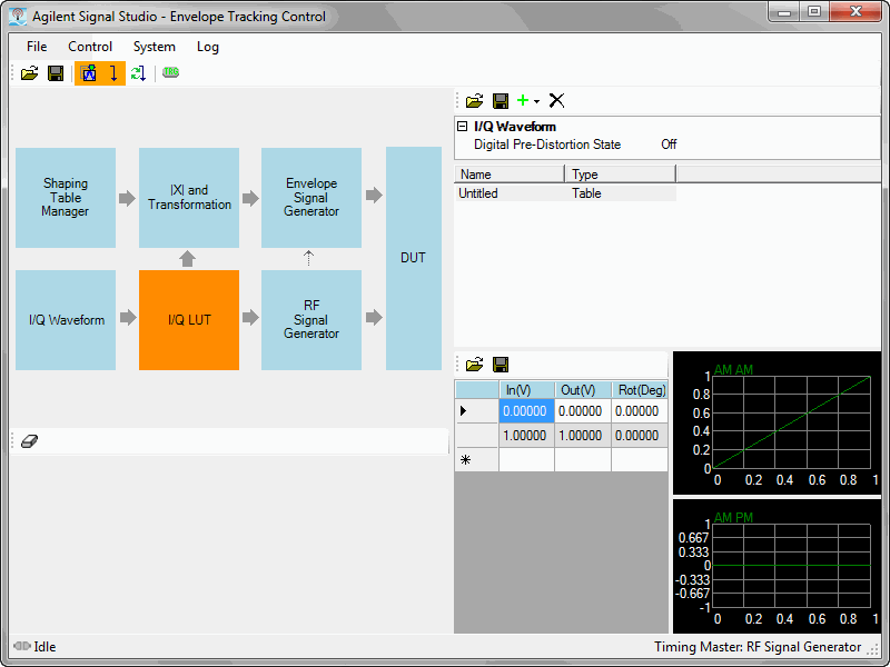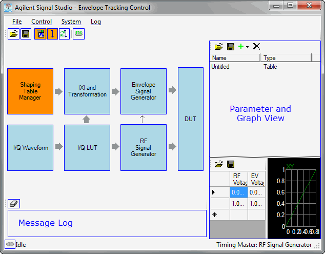
The Envelope Tracking Control window (shown below) is accessed from the software's Tools menu. Click the image for descriptions of the various functions.

Opens an envelope tracking saved settings (.ets) file. Opening an .ets file configures the envelope tracking parameters for use with the currently selected hardware.

Saves the envelope tracking system parameter settings to an *.ets file. Settings files do not include the hardware configuration information, such as LAN or GPIB settings for specific instruments listed in the Hardware node.
The *.ets file stores only the envelope signal generator’s address and configuration. The RF signal generator address and hardware configuration information will not be stored. Settings stored in the *.ets file are also saved in the *.scp/.scpx. files. Neither *.ets or *.scp/.scpx stores RF signal generator settings. You can save all settings, including RF signal generator settings in Quick Setup.
Exports the envelope data to a .csv file type.
Closes the Envelope Tracking Control window and returns you to the Signal Studio window.

Generates a combined envelope and I/Q waveform. The orange background color of this button indicates that the waveform needs to be generated to include any changes you made to waveform parameters. Once the waveform is generated (or regenerated), the button will return to the normal gray background color.

Generates and downloads I/Q waveform and envelope data to the I/Q signal and waveform generators. If the IQ waveform was previously generated, only the envelope data is updated. When generating and updating, output states are turned off for both the RF and the envelope signal generators. After downloading, the On the Fly indicator (connected) turns on. The orange background color of this button indicates that the most recently generated waveform has not yet been downloaded to the instruments. Once the waveform is downloaded, the button will return to the normal gray background color.

Regenerates and downloads I/Q waveform and envelope data to the I/Q signal and waveform generators, even if the IQ waveform was previously generated and downloaded. This is useful in cases where signal generator settings were manually changed on the instrument's front panel, as it forces the connected signal generator to synchronize with the software's current settings.

This button only appears when the RF signal generator is set as the timing master. It sends an ABORT command to the arbitrary waveform generator (AWG), resetting the trigger state. This allows the AWG to receive the trigger and resynchronize with the RF signal generator.

Verifies the connection with the arbitrary waveform generator (AWG).
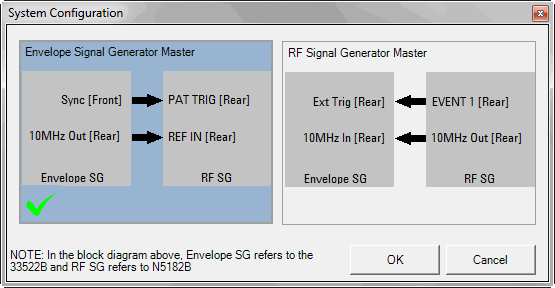
This opens the  System Configuration window. Clicking one of the two available configurations, followed by , determines which source is the timing master, supplying the trigger and 10 MHz reference. The diagram also shows the BNC cable connections for each configuration. The selected timing master configuration appears on the right side of the status bar, located at the bottom of the Envelope Tracking Control window.
Clears the message log in the lower left corner of the Envelope Tracking Control window.
This area displays messages during generate and download process.
This area displays parameters (many are configurable) or graphs, depending on which block of the Envelope Control window is active.

|
Indicates that the On-the-Fly feature is active, enabling real-time parameter updating. If a parameter value is changed, the instrument immediately updates. This feature becomes active after the waveform is generated and downloaded to the instrument. Only then can the state be toggled between Idle and Connected. |

|
Indicates that the On-the-Fly feature is inactive. Click to test the connection and to make the feature active. |
The On-the-Fly feature does not synchronize the instruments. To fully synchronize the instruments, click the Generate and Download button.
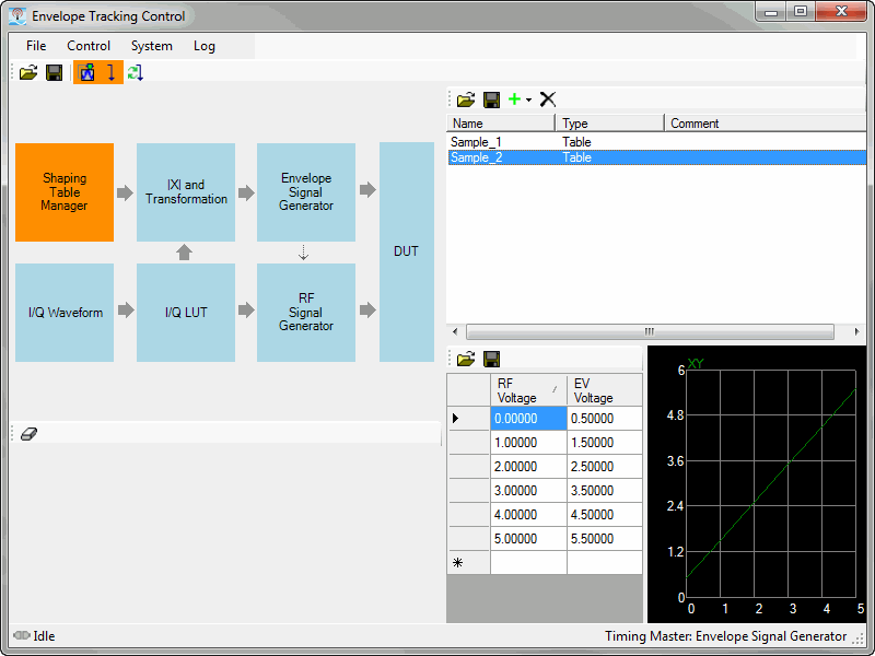
Clicking the Shaping Table Manager block enables you to create and edit shaping tables for the current power amplifier.
| Buttons | Description |
|---|---|
|
|
Opens opens a envelope tracking (.csv) file. |
|
|
Saves the parameters configured in the Envelope Tracking software to a .csv file. |

|
Adds a new table row to the current Envelope Adjust. If "On the fly" is active, the results can be seen in the CCDF graph. |

|
Deletes the currently selected table or formula. |
Click to change a Table or a Formula name.
Indicates Table or Formula for the envelope tracking values.
Optional entry for the Table or Formula description.
Click to change the value in dB input into the PA.
The units on each column are linear voltage. RF Voltage is the I/Q signal (input) and EV Voltage is the envelope signal (output). If the RF voltage value is out of the table range, the nearest table edge value is used for the converted value.
Click to change the value in dB output from the PA.
RF Voltage is the I/Q signal (input) and EV Voltage is the envelope signal (output).
The CCDF graph contains the PA's input vs. output power values.
The |X| and Transformation block enables you to configure and generate the envelope based on the I/Q waveform.
The envelope value of each waveform point is calculated as:

Then oversampling is applied, according to the over sample ratio you select.
Click to generate the envelope data after you have set the envelope generation parameters.
Selects the envelope's data source. This parameter is set automatically by the software to either I/Q Waveform or to Constant Value.
When this parameter is set to Constant Value, the envelope tracking is off and the PA is in normal operation using a constant DC bias voltage. This setting can be used for comparison purposes by manually turning off Envelope Adjust.
Range: 1 to 32
Default: 3
Enter an integer value to set the oversampling ratio for the envelope data.
Choice: On | Off
Default: On
Enables envelope adjust. If Off, then no adjustment is applied to the envelope waveform.
Choice: Absolute RF Output Voltage | Normalized RF Output Voltage
Default: Absolute RF Output Voltage
Use RF output voltage value as conversion table x-axis value. If RF output amplitude is changed, converted data may be changed.
Use normalized power value of IQ waveform data as conversation table x-axis value. Value range is 0 – 1, so that the 0 – 1 range of x-axis are always used for the conversion. RF output amplitude does not affect the conversion.
Apply fixed value (not linked to RF output voltage). The fixed value is set in the parameter, which appears after you make this selection.
Range: –130 dBm to 40 dBm
Default: 10 dBm
This value is used for the rms power level of RF signal for transformation input instead of RF output voltage from RF signal generator amplitude. This parameter appears only when the is set to .
Range: 1 MHz to 200 MHz
Default: 200 MHz
This filter is applied before conversion begins.
The filter cut off range is calculated by:
minimum sampling clock/100
maximum sampling clock/2
If the filter cut off frequency is out of range, the filter is not applied.
The envelope graph displays the first 100 points of the waveform. Increase the oversampling ratio for the envelope as needed to improve the quality of the envelope.
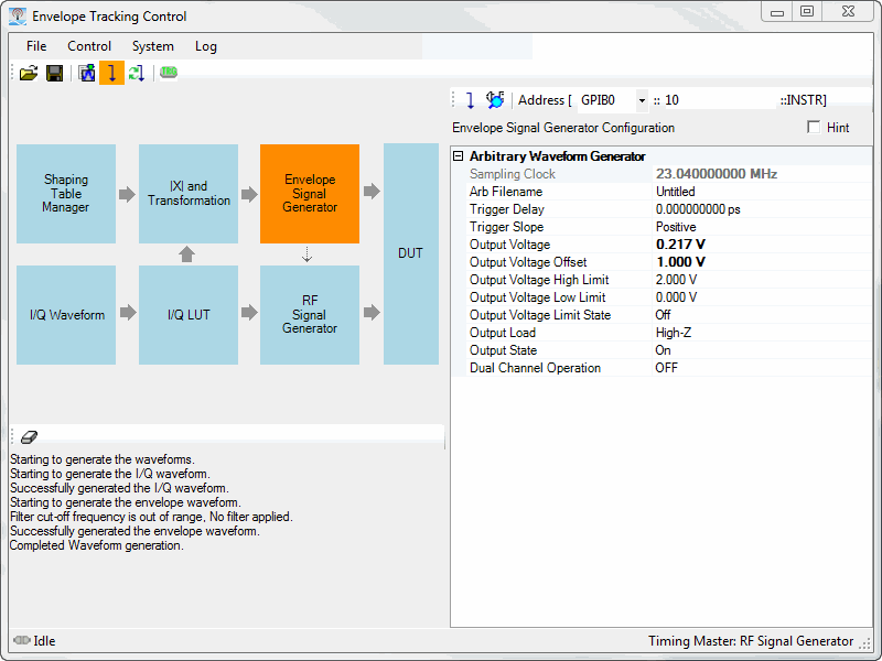
The Envelope Signal Generator block controls the arbitrary waveform generator (33521/22A or 33521/22B). With the On-The-Fly feature activated, changes to parameter values are immediately transmitted to the RF Signal Generator.

This button sends the Envelope Signal Generator configuration parameters to the arbitrary waveform generator.
Verifies the connection with the arbitrary waveform generator (AWG).
Enables connectivity through GPIB, LAN, or USB input connector to trigger an ET waveform. Select the connection type from the drop-down menu, then enter the appropriate address in the adjacent fields.
For all the parameters described in this section, you can also refer to the Keysight 33500 Series Operating and Service Guide.
Range: 1 μSa/s to 250 MSa/s
Default: 40 kSa/s
Sets the sample rate for the arbitrary waveform.
This parameter is coupled to the arbitrary waveform filter command. When the arbitrary waveform filter is set to OFF, then the sampling clock is limited to 62.5 MSa/s. FUNCtion:ARBitrary:FILTer is OFF.
The sample rate and frequency parameter are not coupled when playing an arbitrary waveform segment. The concept of frequency does not apply for arbitrary waveform sequences.
Setting a sample rate when not in the ARB mode will not change the frequency. For example, if the current function is set to sine, then setting the sample rate has no effect until the function changes to ARB.
The maximum sample rate depends on the filter applied to the arbitrary waveform. Refer to FUNCtion:ARBitrary:FILTer and the Keysight 33500 Series Operating and Service Guide for details.
Example of setting the sample rate to 10 kSa/s:
FUNC:ARB:SRAT 1e4
Example of Typical Return:
+1.000000000000000E+04
33521/22B:
[SOURce[1|2]:]FUNCtion:ARBitrary:SRATe <sample_rate>|MINimum|MAXimum
[SOURce[1|2]:]FUNCtion:ARBitrary:SRATe? MINimum|MAXimum
Choices: See MMEMory:LOAD:DATA[1|2], for valid <filename> formats.
Selects an arbitrary waveform (.arb/.barb) or sequence (.seq) that has previously been loaded into volatile memory for the channel specified with MMEMory:LOAD:DATA[1|2] or DATA:ARBitrary. Several waveforms can be in volatile memory simultaneously.
The <filename> should match the filename used to load the arbitrary waveform or sequence into volatile memory with MMEMory:LOAD:DATA[1|2], DATA:ARBitrary, DATA:ARBitrary:DAC, or DATA:SEQuence.
When you store an arbitrary waveform segment or sequence (MMEMory:STORe:DATA[1|2]), the instrument's current settings (voltage values, sample rate, filter type, and so on) are stored in the segment or sequence file. When you play the file for the first time with FUNCtion:ARBitrary, these settings are loaded and override the instrument's current settings. If you have manually edited a segment or sequence file such that the instrument settings have been removed, the instrument settings will not be changed when you execute FUNCtion:ARBitrary.
When you store an arbitrary waveform segment or sequence (MMEMory:STORe:DATA[1|2]), the instrument's current settings (voltage values, sample rate, filter type, and so on) are stored in the segment or sequence file. When you play the file for the first time with FUNCtion:ARBitrary, these settings are loaded and override the instrument's current settings. If you have manually edited a segment or sequence file such that the instrument settings have been removed, the instrument settings will not be changed when you execute FUNCtion:ARBitrary.
Example of setting an arbitrary waveform in memory on channel 2 :
FUNC:ARB "INT:\MyArb103.arb"
Example of a typical return:
"INT:\MyArb103.arb"
Example of loading an arbitrary waveform from the internal drive into volatile memory. Then select and play the waveform.
:MMEM:LOAD:DATA "INT:\BUILTIN\Sinc.arb"
:FUNCtion:ARBitrary "INT:\BUILTIN\Sinc.arb"
:FUNCtion ARB
33521/22B:
[SOURce[1|2]:]FUNCtion:ARBitrary <filename>
[SOURce[1|2]:]FUNCtion:ARBitrary?
Range: 0 to 1000 s (resolution of 4 ns)
Default: 0
Sets trigger delay, (time from assertion of trigger to occurrence of triggered event).
Can be used with IMMediate, EXTernal, or BUS trigger source (TRIGger[1|2]:SOURce).
Example of setting channel 1 trigger delay to 105 ms:
TRIG:DEL 105e-3
Example of Typical Return:
+1.050000000000000E-01
33521/22A and 33521/22B:
TRIGger[1|2]:DELay <seconds|MINimum|MAXimum>
TRIGger[1|2]:DELay?
Choices: Positive | Negative
Default: Positive (rising edge)
Specifies polarity of trigger signal on rear-panel Trig In connector for any externally-triggered mode.
Example setting trigger slope to falling edge:
:TRIG:SLOP NEG
33521/22A and 33521/22B:
TRIGger[1|2]:SLOPe POSitive|NEGative
TRIGger[1|2]:SLOPe?
Range: 1 mVpp to 10 Vpp into 50 Ω
Default: 100 mVpp
Sets output amplitude.
Typical Return:
+5.0000000000000E+00
Set output amplitude to 5 Vpp:
VOLT 5 Vpp
The relationship between offset voltage and output amplitude is shown below. Vmax is the maximum peak voltage for the selected output termination (5 V for a 50 Ω load or 10 V for a high-impedance load).
|Voffset| < Vmax - Vpp/2
If the specified offset voltage is not valid, the instrument will adjust it to the maximum DC voltage allowed with the specified amplitude. From the remote interface, a "Data out of range" error will also be generated.
Differences between remote and front panel operation:
Remote Interface: Setting amplitude from the remote interface can change the offset in order to achieve the desired amplitude. The instrument will generate either a "Data out of range" or "Settings conflict" error. If the specified offset voltage is not valid, the instrument adjusts it to the maximum allowed with the specified amplitude.
Front Panel: Setting amplitude from the front panel will not change the offset setting. If the specified amplitude is not valid, the instrument clips it to the maximum amplitude allowed with the current offset and generates a "Data out of range" error.
Limits Due to Output Termination: If the amplitude is 10 Vpp and you change the output termination setting from 50 Ω to "high impedance" (OUTPut[1|2]:LOAD INF), the displayed amplitude doubles to 20 Vpp. Changing from "high impedance" to 50 Ω halves the displayed amplitude. The output termination setting does not affect the actual output voltage; it only changes the values displayed and queried from the remote interface. Actual output voltage depends on the connected load.
Limits Due to Output Coupling:
Differences between remote and front panel operation: If two channels are coupled, both channels' amplitude limitations will be checked before a change in amplitude is executed. If a change in output amplitude would exceed a LIMIT for either channel, or exceed the instrument's output specifications for either channel:
Remote interface: The instrument will first adjust the offset, then if necessary, the amplitude of that channel to comply with the voltage limits or specification. The instrument will generate either a "Data out of range" or "Settings conflict" error.
Front panel: The instrument will clip the amplitude value to the maximum value with the current offset setting. A "Data out of range" error will be generated.
Specifying Voltage Units: You can set the output amplitude in Vpp, Vrms, or dBm by specifying the units as part of the VOLTage command VOLT 3.0 VRMS.
Use VOLTage:UNIT to specify output units for all subsequent commands.
You cannot specify output amplitude in dBm if output termination is set to high impedance. The units are automatically converted to Vpp.
Limits Due to Units Selection:Amplitude limits are sometimes determined by the output units selected. This may occur when the units are Vrms or dBm due to the differences in various functions' crest factors. For example, if you change a 5 Vrms square wave (into 50 Ω) to a sine wave, the instrument will adjust the amplitude to 3.536 Vrms (the upper limit for sine in Vrms). The remote interface will also generate a "Settings conflict" error.
Arbitrary Waveform Limitations: For arbitrary waveforms, amplitude is limited if the waveform data points do not span the full range of the output DAC (Digital-to-Analog Converter). For example, the built-in "Sinc" waveform does not use the full range of values, so its maximum amplitude is limited to 6.087 Vpp (into 50 Ω).
Changing amplitude may briefly disrupt output at certain voltages due to output attenuator switching. The amplitude is controlled, however, so the output voltage will never exceed the current setting while switching ranges. To prevent this disruption, disable voltage autoranging using VOLTage:RANGe:AUTO OFF. The APPLy command automatically enables autoranging.
You can also set the amplitude (with an associated offset voltage) by specifying a high level (VOLTage:HIGH) and low level (VOLTage:LOW). For example, if you set the high level to +2 V and the low level to -3 V, the resulting amplitude is 5 Vpp, with a -500 mV offset.
To output a DC voltage level, select the DC voltage function (FUNCtion DC) and then set the offset voltage (VOLTage:OFFSet). Valid values are between ±5 VDC into 50 Ω or ±10 VDC into an open circuit. While the instrument is in DC mode, setting amplitude has no effect.
[SOURce[1|2]:]VOLTage {<amplitude>|MINimum|MAXimum}
[SOURce[1|2]:]VOLTage? [{MINimum|MAXimum}]
Range: ± 5 VDC into 50 Ω
Default: 0
Sets DC offset voltage.
Typical Return
+1.0000000000000E-01
Set offset voltage to 100 mV:
VOLT:OFFS 100 mV
The relationship between offset voltage and output amplitude is shown below.
|Voffset| < Vmax - Vpp/2
Differences between remote and front panel operation:
Remote Interface: Setting the offset from the remote interface can change the amplitude in order to achieve the desired offset setting. The instrument will generate either a "Data out of range" or "Settings conflict" error.
Front Panel: Setting the offset from the front panel will not change the amplitude in order to achieve the desired offset setting. If the specified offset is not valid, the instrument will clip it to the maximum offset allowed with the current amplitude and generate a "Data out of range" error.
Limits Due to Output Termination: The offset range depends on the output termination setting. For example, if you set offset to 100 mVDC and then change output termination from 50 Ω to "high impedance," the offset voltage displayed on the front panel doubles to 200 mVDC (no error is generated). If you change from "high impedance" to 50 Ω, the displayed offset voltage will be halved. See OUTPut[1|2]:LOAD for details. Changing the output termination setting does not change the voltage present at the output terminals of the instrument. This only changes the displayed values on the front panel and the values queried from the remote interface. The voltage present at the instrument's output depends on the load connected to the instrument. See OUTPut[1|2]:LOAD for details.
Limits due to Output Coupling: If two channels are coupled, limitations of setting offset will be checked on both channels before a change in offset is executed. If a change in offset would exceed a LIMIT setting, or exceed the instrument's output specifications for either channel:
Remote Interface: First the amplitude and then if necessary, the offset of that channel will be adjusted to comply with the voltage limits or specification. The instrument will generate either a "Data out of range" or "Settings conflict" error.
Front panel: The offset value is clipped to the maximum value allowed that will not exceed the LIMit setting, and a "Data out of range" error will be generated.
Arbitrary Waveform Limitations: For arbitrary waveforms, amplitude is limited if the waveform data points do not span the full range of the output DAC (Digital-to-Analog Converter). For example, the built-in "Sinc" waveform does not use the full range of values, so its maximum amplitude is limited to 6.087 Vpp (into 50 Ω).
Changing amplitude may briefly disrupt output at certain voltages due to output attenuator switching. The amplitude is controlled, however, so the output voltage will never exceed the current setting while switching ranges. To prevent this disruption, disable voltage autoranging using VOLTage:RANGe:AUTO OFF. The APPLy command automatically enables autoranging.
Setting the high and low levels also sets the waveform amplitude and offset. For example, if you set the high level to +2 V and the low level to -3 V, the resulting amplitude is 5 Vpp, with a -500 mV offset.
To output a DC voltage level, select the DC voltage function (FUNCtion DC) and then set the offset voltage (VOLTage:OFFSet). Valid values are between ±5 VDC into 50 Ω or ±10 VDC into an open circuit. While the instrument is in DC mode, setting amplitude has no effect.
[SOURce[1|2]:]VOLTage:OFFSet {<offset>|MINimum|MAXimum}
[SOURce[1|2]:]VOLTage:OFFSet? [{MINimum|MAXimum}]
Same description as Output Voltage Low Limit (see below)
Range: ±5 VDC into 50 Ω, as long as HIGH is at least 1 mV greater than LOW.
Defaults: HIGH +50 mV, LOW -50 mV
Sets the high and low limits for output voltage.
For voltage limits to be in effect, VOLTage:LIMit:STATe must be ON (VOLT:LIMIT:STATE ON). If this is the case, and the high limit is set below the high value of the signal or the low limit is set above the low value of the signal, the relevant limit will be clipped to the high or low value of the signal. The instrument will generate either a "Data out of range" or "Settings conflict" error.
The high limit sets the highest output voltage allowed to be set, including DC Offset and peak amplitude. It is set in reference to the current OUTPUT[1|2]:LOAD setting. If the specified LOAD impedance is not present at the instrument's output, then the output limit may not represent the actual voltages at the output connector. For Example, if the output impedance is set to 50 Ω, but the actual load is high impedance, then the actual output peak voltage may be up to twice the specified limit voltage.
Specifying Voltage Units: You can set the output limit voltage only in volts.
When VOLTage:COUPle[:STATe] is ON, and VOLTage:LIMit:STATe is ON, voltage limit settings on both channels affect maximum amplitude and offset voltage settings.
Example of setting voltage limit high to 5.0V:
VOLT:LIMIT:HIGH 5.0
Example of Typical Return:
+5.0000000000000E+00
33521/22A and 33521/22B:
[SOURce[1|2]:]VOLTage:LIMit:HIGH <voltage>|MAXimum|MINimum
[SOURce[1|2]:]VOLTage:LIMit:HIGH? MAXimum|MINimum
[SOURce[1|2]:]VOLTage:LIMit:LOW <voltage>|MAXimum|MINimum
[SOURce[1|2]:]VOLTage:LIMit:LOW?
Choices: On | Off
Default: Off
Enables or disables output amplitude voltage limits.
When this parameter is turned ON, if the present settings of amplitude and offset exceed the limits, then the limits will be disabled. The instrument will generate either a "Settings conflict" error.
When VOLTage:COUPle[:STATe] is ON, and VOLTage:LIMit:STATe is ON, voltage limit settings on both channels affect maximum amplitude and offset voltage settings on both channels. The most restrictive combination of high and low limits from either channel is used.
Limits are set in reference to the current setting of OUTPut[1|2]:LOAD. If the specified LOAD impedance is not present at the instrument's output, then the output limit may not represent the actual voltages at the output connector. For example, if the output impedance is set to 50 Ω, but the actual load is high impedance, then the actual output peak voltage may be up to twice the specified limit voltage.
Example of setting and enabling ±2.5 V output limits on channel 1:
VOLT:LIM:HIGH 2.5
VOLT:LIM:LOW -2.5
VOLT:LIM:STAT ON
Example of typical return:
0 (OFF) or 1 (ON)
33521/22A and 33521/22B:
[SOURce[1|2]:]VOLTage:LIMit:STATe ON|1|OFF|0
[SOURce[1|2]:]VOLTage:LIMit:STATe?
Choices: 50 | INF
Default: 50
Sets expected output termination. Should equal the load impedance attached to the output.
The specified value is used for amplitude, offset, and high/low level settings.
The instrument has a fixed series output impedance of 50 Ω to the front-panel channel connectors. If the actual load impedance differs from the value specified, the displayed amplitude and offset levels will be incorrect. The load impedance setting is simply a convenience to ensure that the displayed voltage matches the expected load.
If you change the output termination setting, the displayed output amplitude, offset, and high/low levels are adjusted (with no error generated). If the amplitude is 10 Vpp and you change the output termination setting from 50 Ω to "high impedance" (OUTPut[1|2]:LOAD INF), the displayed amplitude doubles to 20 Vpp. Changing from "high impedance" to 50 Ω halves the displayed amplitude. The output termination setting does not affect the actual output voltage; it only hanges the values displayed and queried from the remote interface. Actual output voltage depends on the connected load.
You cannot change the output termination setting with voltage limits enabled; the instrument cannot know which output termination settings the voltage limits apply to. To change the output termination setting, disable voltage limits, set the new termination value, adjust voltage limits, and re-enable voltage limits.
If INF (high impedance) is selected, the query returns 9.9E+37.
Choices: On | Off
Default: Off or On
Enables or disables the front-panel output connector.
When output is enabled, the front-panel channel output key is illuminated.
The APPLy commands override current OUTPut setting and enable the channel output connector.
If excessive external voltage is applied to the front-panel channel output connector, an error message appears and output is disabled. To re-enable output, remove overload from the output connector and send OUTPut ON.
OUTPut changes the state of the channel output connector by switching the output relay, without zeroing output voltage. Therefore, output may glitch for about a millisecond until signal stabilizes. Minimize glitching by first minimizing amplitude (VOLTage MIN) and setting offset to 0 (VOLTage:OFFSet 0) before changing output state.
Example of typical return for an enabled output connector for channel 1:
OUTP ON
33521/22A and 33521/22B:
OUTPut[1|2] ON|1|OFF|0
OUTPut[1|2]?
Choices: On | Off | Inverted
Causes channels 1 and 2 of a two-channel instrument to output the same signal, or an inverted polarity signal.
Causes all settings of the named channel to be copied to the other channel with exceptions noted below. This does include frequency list settings and any arbitrary waveforms loaded in memory.
With the INVerted option, the tracking channel's amplitude will be inverted, forming a signal similar to a differential output between Channel 1 and Channel 2. DC Offset is not inverted.
When TRACk is ON, voltage limits on both channels apply. If voltage limits on either channel would prevent the other channel's setup from being applied, the instrument will generate a settings conflict error and channel tracking will remain OFF.
When TRACk is ON, changes to either channel are reflected in both channels. When TRACk is changed from ON or INV to OFF, the channels will remain in their present setup (frequency, amplitude, and so on), but you may now change one channel without affecting the other channel.
Voltage limits may be adjusted in tracking mode, but cannot be set in violation of the current signal.
Turning tracking ON sets COMBine:FEED to NONE, turns off FREQuency:COUPle, VOLTage:COUPle, and RATE:COUPle.
TRACK is not allowed if the internal modulation source for the channel being tracked is the other channel.
The OUTPut:SYNC:SOURce is set to the channel being tracked.
Example of typical return:
ON, OFF, or INV
Example of setting channel 2 output signal identical to so that of channel 1:
TRACk ON
33521/22A and 33521/22B:
[SOURce[1|2]:]TRACk ON|OFF|INVerted
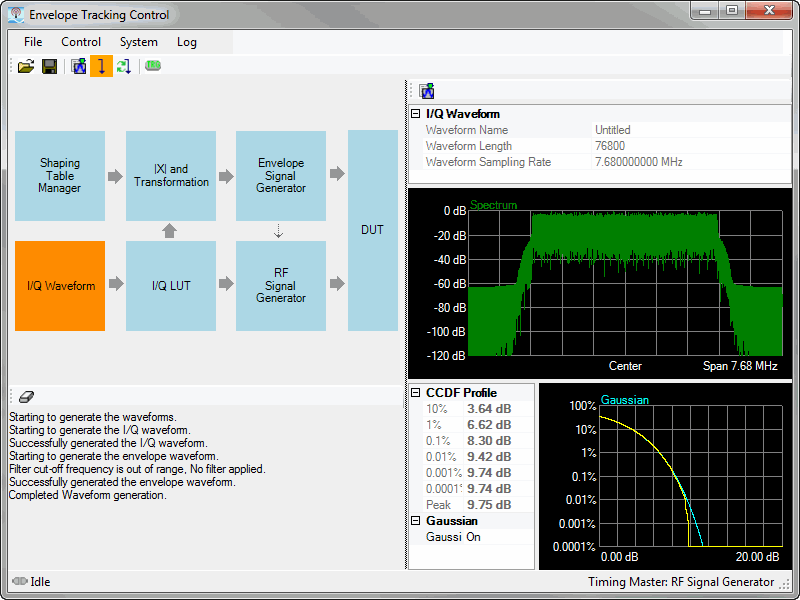
The I/Q Waveform block is read-only, so parameters are not editable here. If you need to change some of the I/Q waveform parameters, close the Envelope Tracking Control window and make the changes in the main software window.
Generates a combined envelope and I/Q waveform. This performs the same function as the Generate button on the ET control window's tool bar.
Sets the Waveform filename. This parameter is not editable within the Envelope Tracking software.To edit this parameter, close the Envelope Tracking Control window and make any edits in the Signal Studio software.
The Waveform Name parameter is editable in the Waveform Setup node.
Sets the Waveform Length. This parameter is not editable within the Envelope Tracking software.To edit this parameter, close the Envelope Tracking Control window and make any edits in the Signal Studio software.
The Waveform Length value is not directly editable. To edit the Waveform Length (Total Sample Points), click on the Oversampling Ratio parameter. The Waveform Length (Total Sample Points) is automatically determined based on the oversampling ratio. Using a larger oversampling ratio results in a more completely filtered image, but also uses more waveform memory by increasing the number of waveform points. Refer to the Carrier n node, for your 3GPP release version of carrier.
Sets the Waveform Sampling Rate. This parameter is not editable within the Envelope Tracking software.To edit this parameter, close the Envelope Tracking Control window and make any edits in the Signal Studio software.
Waveform Sampling Rate is a sampling rate without Oversampling Ratio (OSR) which is set by the Carrier n node's Base Sampling Rate parameter. Refer to the Carrier n node's Base Sampling Rate parameter for a more complete description.
The I/Q LUT block provides quick and convenient access to digital pre-distortion (DPD) control and lookup table (LUT).
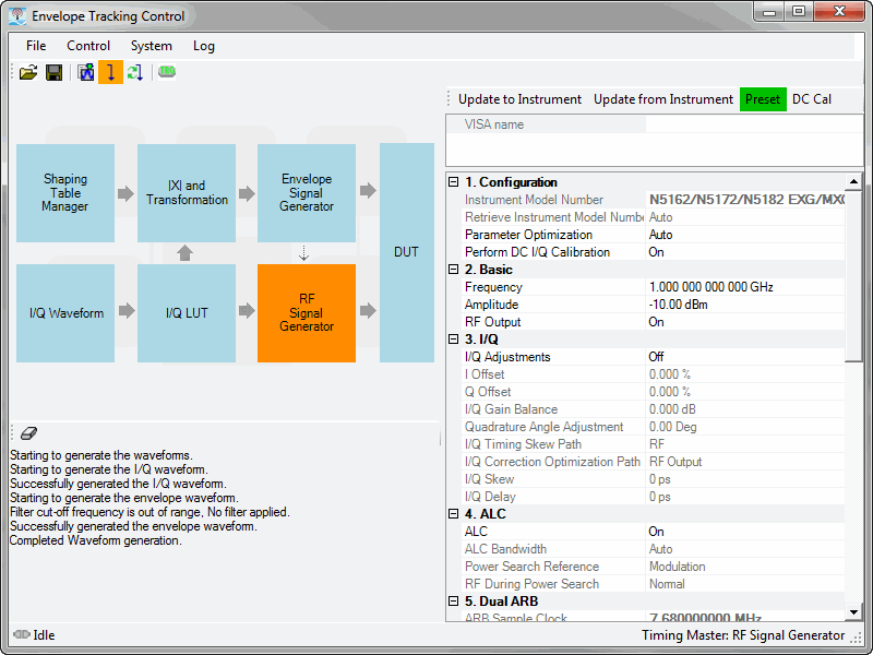
The RF Signal Generator block is editable and represents the Signal Studio's instrument node.For the list of parameters and descriptions, refer to the instrument node.
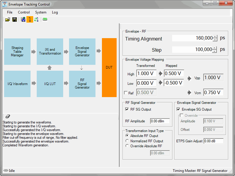
The DUT block allows you to set envelope timing alignment and map envelope voltage levels into the DUT. All parameter adjustments happen in real time while the On-The-Fly feature is enabled.
Adjusts the timing between RF signal generator and Envelope signal generator.
This parameter will distribute to Trigger delay (RF Signal Generator) and IQ_DELAY (RF Signal Generator).
SYNC signal of Envelope SG is source of trigger for the RF signal generator.
Delay value = trigger delay (RF SG) + IQ_DELAY (RF SG).
For Negative delay value, add one waveform length timing to the delay value.
This step number used for increment/decrement the timing adjusts value by using mouse wheel or up/down control. Step can be changed.
This section describes individual parameters. For more information, see ETPS Input Voltage Mapping.
This is the high voltage value of the shaping table and will be converted to the Mapped High value.
This is the low voltage value of the shaping table and will be converted to the Mapped Low value.
Check this box to override the automatic calculated reference level with the current value, which you can edit. This value is the swing center of the envelope and and Vcm point (with offset). If the box is not checked, the transformed reference value is calculated as follows:
Transformed High – Transformed Low)/2
This is the high peak-voltage value (positive swing) of the envelope waveform data input to the envelope tracking power supply (ETPS), converted from the Transformed High value.
This is the low peak-voltage value (negative swing) of the envelope waveform data input to the envelope tracking power supply (ETPS), converted from the Transformed Low value.
This read-only field shows the peak-to-peak mapped voltage value, calculated as follows:
Vpp = Mapped High voltage – Mapped Low voltage
This is the common-mode voltage and is mapped to the center of the envelope waveform swing (peak-to-peak amplitude). This value also includes any offset value applied.
Check this box to turn on the RF signal generator output.
Sets the RF power of the RF signal generator.
Use RF output voltage value as conversion table x-axis value. If RF output amplitude is changed, converted data may be changed.
Use normalized power value of IQ waveform data as conversation table x-axis value. Value range is 0 – 1, so that the 0 – 1 range of x-axis are always used for the conversion. RF output amplitude does not affect the conversion.
Apply fixed value (not linked to RF output voltage). Enter the fixed value in the field directly below this button.
Check this box to turn on the envelope signal generator output.
Check this box to override the envelope signal generator output voltage and offset. If overridden, the amplitude and offset values are not automatically calculated from mapped Vpp and Vcm.
See Output Voltage.
Adjusts the output voltage in dB.
For example, if set to –6 dB, the output voltage will be one half.