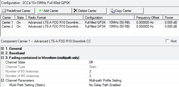
Additional parameter setup tables for the downlink carrier are described in General (Advanced LTE-A FDD Downlink) and Baseband (Advanced LTE-A FDD Downlink).
Fading parameters are not available when the Waveform Generation Length parameter is set to >160 ms.

|
3. Fading contained in Waveform |
|---|
Choice: Off | On
Default: Off
Double-click or use the drop-down menu to turn the channel on or off.
Channel State Off - The software simulates the signal at the base station transmitter antenna.
Channel State On - The software simulates the signal at the mobile station receiver antenna.
When the channel state is on, enable at least one path in the Multipath Configuration window. See Multi-Paths Setting (Static).
For multiple signal generator configurations, you must turn the Channel State on before you can change the number of BS antennas using the Total number of Antennas parameter in the eNB Setup node. When the channel state is off, you must change the number of signal generators (for example, Quick Setup M x 1, M x 2, M x 4) to change the number of BS antennas.
Choice: Mobile | Static
is not available in this Signal Studio release.
Displays the number of base station antennas.
For multiple signal generator configurations, you must turn the Channel State on before you can change the number of BS antennas using the Total number of Antennas parameter in the eNB Setup node. When the channel state is off, you must change the number of signal generators (for example, Quick Setup M x 1, M x 2, M x 4) to change the number of BS antennas.
Displays the number of mobile station antennas.
This value is set by the software to the number of signal generators configured in your physical or simulated hardware (SimHW) setup.
Click the  icon to display the available channel parameters.
This parameter is active when the Channel Type is set to Static.
Click on the  button in the cell to open the Multipath Configuration window,
which enables you to add up to 20 paths with delay, power, and phase impairments
to simulate the multi-point reflection experienced in a real-world multipath
environment. Use the editing table to enable or disable individual paths
as needed for fine-tuning.
Note that there are tabs for each channel, for example, channel H10 for the channel from Tx Antenna 1 to Rx Antenna 0. Click the arrows to display additional tabs.
The following impairments can be made to each path:
Delay (0 to 20000 ns) - A reflected signal bounces off of one or more surfaces before reaching the receiver, resulting in a longer path than the line-of-sight signal. Therefore, the reflected signal experiences some amount of delay, relative to the line-of-sight signal.
The minimum resolution for the Delay value is dependent on the sampling rate (oversampling rate), as follows: minimum resolution = 1/(sample rate).
For LTE, the default minimum resolution is 1/(61.44 MHz) = 16.27 ns. A delay value entry that is less than half the minimum resolution (< 16.27 ns/2) is rounded to 0 ns by the software. A delay value entry that is greater than half the minimum resolution (> 16.27 ns/2) is rounded to 16.27 ns by the software. For example, entering 3 ns or 5 ns will result in 0 ns of delay; entering 9 ns or 11 ns will result in 16.27 ns of delay. The same rounding process applies in each successive 16.27 ns interval.
Changing the oversampling rate results in a corresponding change to the minimum resolution.
Power (-100 to 0 dB) - Power Attenuation occurs with reflected signals as a result of the added distance they travel, compared to the line-of-site signal. Other factors may also contribute to signal power attenuation, such as the characteristics of the reflecting surface.
Phase (-360 to 360 Deg) - Signals become distorted as they reflect off of walls or other surfaces or wrap around corners, causing a shift in phase relative to the line-of-site signal. You can adjust the phase of each multipoint signal to simulate such distortions.
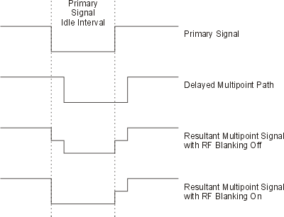
When enabling a multipath configuration, it is best to turn off RF Blanking. Leaving Blanking on can result in partial blanking of any delayed multipaths (see the figure below). To disable RF Blanking, click the in the tree view and set the RF Blanking to . You can also turn off RF blanking on the signal generator after the waveform file has been downloaded.
