The N7625C Signal Studio Pro for LTE/LTE-Advanced TDD 2026 software enables you to generate a Continuous Waveform (CW) carrier.
A typical receiver measurement is the receiver's ability to continually demodulate in the presence of an interferer signal. These signals are often simulated with a CW blocker. Using the N7625C you can generate one or more CW signals for these types of measurements.
Typically, the wanted signal is at a lower power level than the unwanted signal (interferer). As the dynamic range increases between the wanted and unwanted signals, the EVM for the wanted signal is degraded.
In some cases, better RF performance is required or you may need a dynamic range that is greater than the software's -60 dBm dynamic range. For these cases, additional signal generators can be used to generate the CW interferer waveforms and to then combine the waveforms in RF to minimize the intermodulation products and to improve EVM performance.
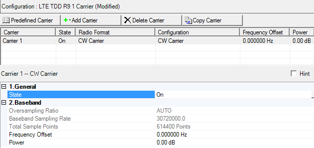
In the figure below, a Continuous Waveform is selected for configuration.

|
1. General |
|---|
|
2. Baseband |
Double-click or use the drop-down menu to control the operating State of the UL-SCH carrier
This is a read only parameter. This parameter is not editable.
Displays the Baseband Sample Rate. This parameter is not editable.
View the Waveform Length, displayed in points.This parameter is not editable.
Waveform Length is directly related to the Oversampling Ratio value selected. The higher the Oversampling Ratio, the larger the waveform.
Range: -76.8 MHz to 76.8 MHz
Default: 0 Hz
Sets the frequency offset for the carrier relative to the signal generator’s frequency setting.
This parameter is coupled with Oversampling Ratio.
| Maximum Arb Sample Clock (RF Bandwidth) | Maximum Frequency Offset |
|---|---|
| 75 MHz (60 MHz) | 15.36 MHz |
| 100 MHz (80 MHz) | 30.72 MHz |
| 125 MHz (100 MHz) | 46.08 MHz |
| 150 MHz (120 MHz) | 46.08 MHz |
| 200 MHz (160 MHz) | 76.8 MHz |
Range: -60.000 to 20.000 dB
Default: 0.000 dB
Sets the carrier’s power relative to the signal generator’s amplitude setting.