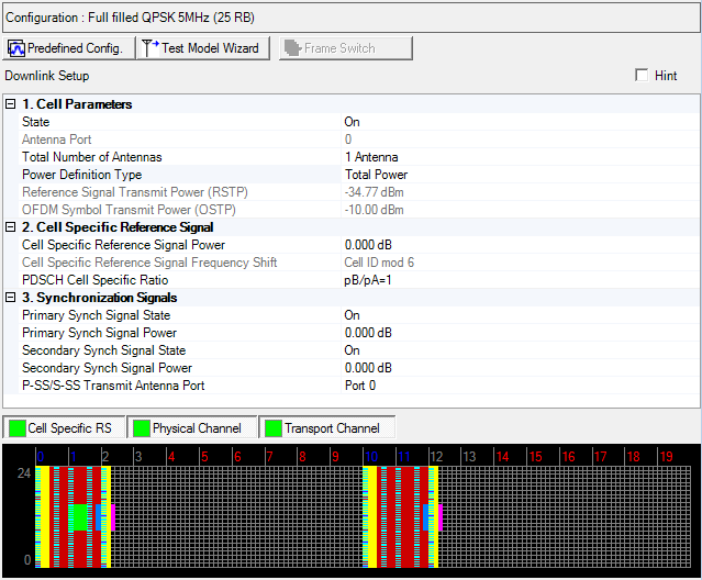
Click the Predefined Configuration button to access a ![]() dialog box
from which you can select a base channel configuration.
dialog box
from which you can select a base channel configuration.
The Test Model Wizard button opens a window from which you can select a test model type and set or view other related parameters. In the ETM test Mode, it will generate with two different frame settings.

Click the Frame Switch button to see the settings for different frames.
Click the links in the tables below to view parameter descriptions.
|
1. Cell Parameters |
2. Cell Specific Reference Signal |
3. Synchronization Signals |
|---|---|---|
|
|
P-SS/S-SS Transmit Antenna Port | |
|
|
|
Choice: On | Off
Default: On
Double-click or use the drop-down menu to turn the downlink transmission off or on.
Default: 0
In multi-antenna configurations, specify the antenna to be used for transmitting the downlink signal. The available selections are determined by the Total Number of Antennas setting.
In multi-antenna configurations, specify the total number of antennas used for downlink transmission.
For multiple signal generator configurations, set the Channel State parameter in the Fading section of the Carrier node to On to make this cell active. When the channel state is off, you must change the number of signal generators (for example, Quick Setup Mx1, Mx2, Mx4) to change the number of BS antennas.
Choice: Total Power | RSTP
Default: Total Power
Double-click or use the drop-down menu to select the power definition type.
If Total Power is selected, power reference is Amplitude parameter on Instrument node. In this case, RSTP and OSTP are automatically calculated by Amplitude parameter on Instrument node, Power parameter on Carrier node and each carrier signal settings.
If RSTP is selected, power reference is RSTP. In this case, Amplitude on Instrument node and OSTP are calculated by RSTP, Power parameter on Carrier node and each carrier signal settings.
In multiple carrier case, Power Definition Type parameter in each carrier should be same.
Range: -15.00 to -144.00 dBm
Default: -34.77 dBm
Enter the Reference Signal Transmit Power in dBm, when the Power Definition Type is RSTP. Otherwise displays the Reference Signal Transmit Power in dBm and the value is updated after generation.
Available setting range and step depends on hardware.
See 3GPP TS 36.141 for more information.
Display the Downlink OFDM Symbol Transmit Power in dBm.
For detailed information about OSTP, refer to the 3GPP TS 36.141.
Range: -60 to 20 dB
Default: 0 dB
Enter a power level in dB for the cell specific reference signal.
The software maps cell specific reference signal symbols to resource elements in compliance with 3GPP technical specification TS 36.211. The Cell specific Reference Signal Frequency Shift parameter is set by the software to control the reference signal offset in each subframe.
The applied frequency offsets are indicated in the resource mapping graph.
For detailed information about reference symbol mapping, refer to the 3GPP TS 36.211 V8.4.0 document at http://www.3gpp.org.
Choice: pB/pA=1 | P_B=0 | P_B=1 | P_B=2 | P_B=3
Default: pB/pA=1
Double-click or use the drop-down menu to select the PDSCH cell specific ratio.
Choice: Off | On
Default: On
Double-click or use the drop-down menu to turn the primary synchronization signal (P-SS) On or Off.
Range: -60 to 20 dB
Default: 0 dB
Enter the power level in dB for the primary synchronization signal.
Choice: Off | On
Default: On
Double-click or use the drop-down menu to turn the secondary synchronization signal (S-SS) On or Off.
Range: -60 to 20 dB
Default: 0 dB
Enter the power level in dB for the secondary synchronization signal.
Choice: Port 0 | Port 1 | Port 2 | Port 3 | All Ports
Default: Port 0
Double-click or use the drop-down menu to select the P-SS/S-SS Transmit Antenna Port type.