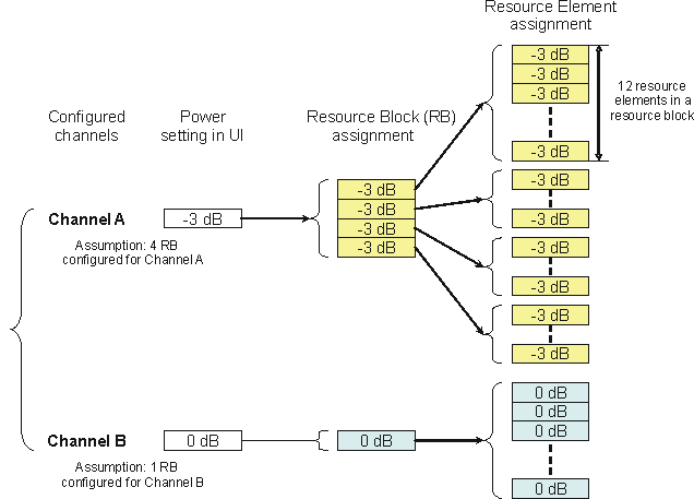
The software applies the power settings you define for data channels (for example PDSCH) to all resource elements in the resource blocks occupied by the data channel. This is illustrated in Figure 1.

Figure 1. Data Channel Power Assignment to Resource Blocks
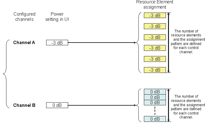
The software applies the power settings you define for control channels (for example PDCCH) to the specific resource elements occupied by the control channel. This is illustrated in Figure 2.

Figure 2. Control Channel Power Assignment to Resource Elements
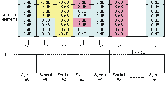
The output power is calculated for each OFDM symbol by accumulating the power levels assigned to each subcarrier (resource element) for that symbol. Subcarrier power settings are defined using the Power parameter in the Transport Channel, Physical Channel, and Resource Block nodes (see Power Settings).

Figure 3. Symbol-by-Symbol Power Calculation
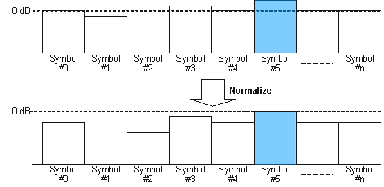
The symbol with the highest calculated power level is used as the 0 dB reference and the calculated power levels for the other symbols are normalized to the 0 dB reference as shown in Figure 4. The signal generator output power is determined by the normalized power for each symbol.

Figure 4. Normalizing Power
The symbol that has the highest power level in the waveform is used as the reference for the signal generator output power level (i.e. In the example above it is symbol #5). Also, there could be multiple symbols in the waveform with this power level. This symbol (or symbols) will have an RMS power level which is displayed on the instrument front panel as the RF power level. Therefore, if an average power measurement is made over the entire waveform using a signal analyzer or power meter, the measured power level will be lower, especially in configurations where some of the symbols have a large power delta or some of the subframes have been turned off in a waveform.
To measure the displayed RMS power of the waveform more accurately, use the time gating feature available on a signal analyzer or an advanced demodulation tool (e.g. 89600 series software).
Example: Again, using the images above, if the signal generator is set to -10 dBm, then symbol #5 is going to be set to a RMS of -10 dBm, and all of the other symbols will have a lesser power value. Therefore, if an average power level is made at the RF output on the signal generator, it will measure < -10 dBm. And, if some of the waveform's subframes are turned off, the resulting power measured on the output of the signal generator's RF output could measure much lower power than -10 dBm.
In the case of MIMO, all of the SISO conditions mentioned above would apply. But, with multiple antennas, the antenna(s) with the highest symbol or symbols power would be used as the reference for the MIMO signal. All other antennas would have a lower power level relative to the reference highest power antenna(s).