This topic describes the following configurations:

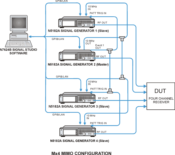
Figure 1. Using four MXG/EXG X-Series signal generators
Figure 1 shows you how to set up four X-Series signal generators (either N5182A, N5172B, or N5182B) for the Multiple Antennas Solution with Baseband Timing Alignment, but without RF Phase Coherence.
You can use multiple N5182A signal generators in the same system, or you can use N5172B and N5182B signal generators in the same system. However, you cannot use a mixture of N5182A signal generators and N5172B or N5182B signal generators in the same system.
If you are using an N5172B or N5182B and one or more N5182A signal generators, you must configure the N5172B or N5182B as the Master. In addition, the N5182A slaves must be at the end of the instrument chain.
The X-Series signal generator provides precise baseband timing alignment as a standard feature, which synchronizes the start of the BBG waveform playback of up to 16 signal generators. For the N5182A, or N8300A, the playback is synchronized to within a characteristic value of ± 8 ns between the master and the last slave. For the N5172B or N5182B, the playback is synchronized to within a characteristic value of ± 5 ns between the master and the last slave. This minor amount of delay (± 8 ns or ± 5 ns) can be reduced further to picosecond resolution by adjusting the I/Q Delay. To reduce the delay, check and adjust the BBG signal alignment for each signal generator in the system. For more information on adjusting the delay, see ”I/Q Adjustments” in the MXG/EXG X-Series user's guide.
The delay value includes compensation for cables that have less than 1 ns of propagation delay between the EVENT 1 and PAT TRIG connectors. To minimize synchronization delay, the Keysight BNC cable 10502A is the recommended cable for the rear-panel daisy chain connections.
The Event 1 connector on the master MXG/EXG rear panel is connected to the Pattern Trigger In connector on the slave MXG/EXG. This ensures that the two baseband generators are precisely synchronized at the start of the waveform playback. Synchronization occurs after the master signal generator sends a one-time event pulse through the Event 1 connector to the slave signal generator. Prior to this event, the slave signal generator must recognize that it is waiting for this event pulse, which occurs during the system configuration (see "Multiple Baseband Generator Synchronization" in the MXG/EXG X-Series user's guide. In order to properly send the synchronization pulse, the Dual ARB Player for each signal generator must be turned off. The trigger source on both signal generators is automatically set by the software. On the master MXG/EXG, it is set to "Bus" to wait for a SCPI command trigger through the GPIB or LAN bus. On the slave MXG/EXG, it is set to "External" to receive a trigger through the rear-panel PAT TRIG connector.
When you start the Signal Studio software, you will need to choose a multiple antenna configuration (M x 4 in this example) in the System Configuration Wizard. You will be asked for connection information for the corresponding number of MXG/EXG signal generators. The signal generators must have a valid license for Advanced Capability in order to have access to most of the software features for multiple antennas. Once you have connected to the MXG/EXG signal generators, the software will send the SCPI commands to the signal generators and will automatically finish the system configuration that is required by the synchronization process. This process is listed in "Multiple Baseband Generator Synchronization" in the MXG/EXG X-Series user's guide.
When you generate the waveforms for multiple antennas, the Signal Studio software pre-calculates the waveform packets and applies the effects of specific channels, then loads the composite waveform into each signal generator.

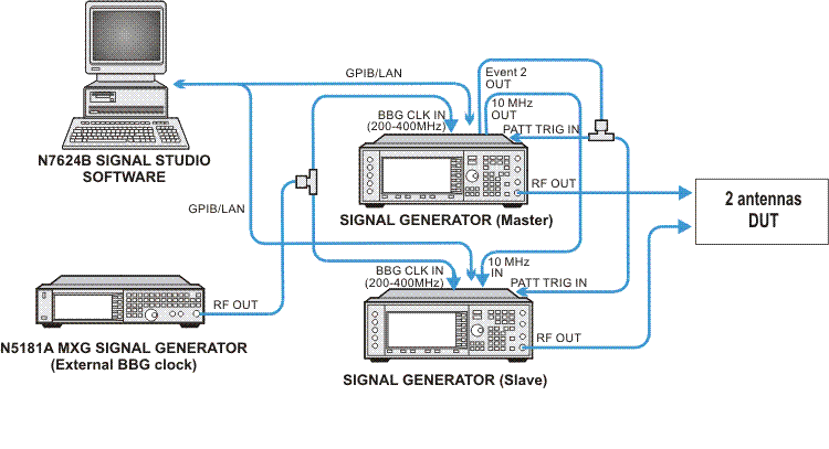
Figure 2. Using two E4438C ESG signal generators
Figure 2 shows you how to set up two ESG signal generators for the Multiple Antenna Solution with Baseband Timing Alignment, but without RF Phase Coherence.
When using E4438C ESG signal generators, each requires special option HEC to provide the external baseband generator clock input on the rear panel. Connect a cable from the 10 MHz OUT connector on the master signal generator to the 10 MHz IN connector on the slave. An N5181A MXG signal generator is used as an external common clock for the two baseband generators to ensure timing alignment of the baseband signals. The Event 2 connector on the master signal generator is connected to the Pattern Trigger In connector on each of the two signal generators. This ensures that the two baseband generators are triggered simultaneously, eliminating time errors in the waveform output. The synchronization occurs immediately after downloading the waveforms to both signal generators. The Signal Studio software will send a SCPI command to the master signal generator to direct it to send a one-time event pulse through the Event 2 connector to itself and to the slave signal generator. Then, this pulse signal triggers the two signal generators to simultaneously play back the waveform.
The EVENT 2 signal works as both a Trigger Source and an actual Marker 2 output signal. Before the waveform playback, EVENT 2 serves as the trigger source. After waveforms are triggered to play back, EVENT 2 no longer functions as a trigger source, but as a Marker 2 output, whenever marker 2 is present in the waveform.
When you start the Signal Studio software, choose a multiple antenna configuration (M x 2 in this example) in the System Configuration Wizard. You will be asked for connection information for the corresponding number of signal generators. Both signal generators must be the same model and both must have a valid license for Advanced Capability in order to have access to most of the software features for multiple antennas.
When you generate the waveforms for multiple antennas, the Signal Studio software pre-calculates the waveform packets and applies the effects of specific channels, then loads the composite waveform into each signal generator and applies it directly to the DUT.