Channels

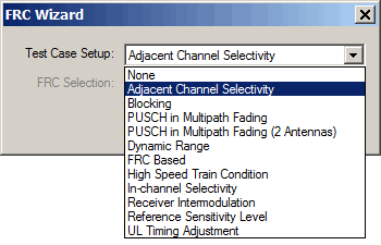
Test case and FRC for base station conformance test are set in the FRC Wizard dialog box, and the selected test case setup and FRC are displayed in the 1. FRC Parameter Setup part.

When using multiple instruments as shown in the tree view, inaccurate test data may occur if a combination of the GUI and SCPI is used to set or modify the instrument and test parameters. The software will not reflect changes made outside of the GUI even with the use of the Update from Instrument button. For all tests, use only one method to configure the settings, GUI or SCPI.

When configuring multiple instruments with SCPI instead of using the GUI, the commands must be executed for each instrument.

When using multiple instruments as shown in the tree view, after clicking the State On button, all settings for this window gray out and cannot be changed. To change the settings, first click the State Off button.

Buttons

This button indicates that the current real-time settings have been applied to the instrument—no action is required. This button is not available when the Apply Needed button is active. When using multiple instruments as shown in the tree view, this button is not displayed.

This button displays in place of the Settings Current button. It indicates that the instrument settings are not currrent and need to be updated with the new software settings. Click this button to update the insturment's settings. This button shows in all windows regardless of where the change was made. When using multiple instruments as shown in the tree view, this button is not displayed.

[:SOURce]:RADio:LTE:TDD[:BBG]:ULINk:APPLy

[:SOURce]:RADio:LTE:TDD[:BBG]:ULINk:APPLy?

[:SOURce]:RADio:LTE:TDD[:BBG]:ULINk:TPARameter:FRC:[:SET] <TestCase>,<FrcTable>

Refer to the FRC Test Table below for the SCPI arguments.

[:SOURce]:RADio:LTE:TDD[:BBG]:ULINk:TPARameter:FRC:TCASe?

[:SOURce]:RADio:LTE:TDD[:BBG]:ULINk:TPARameter:FRC:TABLe?

[:SOURce]:RADio:LTE:TDD[:BBG]:ULINk:TPARameter:FRC[:SET]?

This query checks whether any of the following parameters have changed since setting the test case and FRC table. If changes have not been made, the query returns NMODified (not modified), otherwise it returns MODified.

LTE TDD Uplink Node
PUSCH Node
UL - SCH Node

FRC Test Table

The table below shows the available FRC Selections (<TestCase>,<FrcTable>) for different test case setup and system bandwidth combinations. System bandwidth is set under LTE TDD Uplink node in the tree view. For more details about FRC, refer to Annex A of 3GPP TS 36.141.

Test Case Setup\

System bandwidth

1.4 MHz

3 MHz

5 MHz

10 MHz

15 MHz

20 MHz

None

None

None

None

None

None

None

GUI: Adjacent Channel Selectivity

SCPI: ACSelect

A1-1

A1-2

A1-3

A1-3

A1-3

A1-3

GUI: Blocking

SCPI: BLOCking

A1-1

A1-2

A1-3

A1-3

A1-3

A1-3

GUI: PUSCH in Multipath Fading

SCPI: PMFading

A3-1, A3-2

A4-1, A4-2, A4-3

A5-1, A5-2

A3-1, A3-3

A4-1, A4-2, A4-4

A5-1, A5-3

A3-1, A3-4

A4-1, A4-2, A4-5

A5-1, A5-4

A3-1, A3-5

A4-1, A4-2, A4-6

A5-1, A5-5

A3-1, A3-6

A4-1, A4-2, A4-7

A5-1, A5-6

A3-1, A3-7

A4-1, A4-2, A4-8

A5-1, A5-7

GUI: PUSCH in Multipath Fading (2 Antennas)

SCPI: PMF2A

A3-2

A4-3

A3-3

A4-4

A3-4

A4-5

A3-5

A4-6

A3-6

A4-7

A3-7

A4-8

GUI: Dynamic Range

SCPI: DRANge

A2-1

A2-2

A2-3

A2-3

A2-3

A2-3

GUI: FRC Based

SCPI: FRCBased

A1-1, A1-4

A2-1

A3-1, A3-2

A4-1 to A4-3

A5-1, A5-2

A7-1, A7-2

A8-1, A8-2

A1-1, A1-2, A1-4, A1-5

A2-1, A2-2

A3-1 to A3-3

A4-1 to A4-4

A5-1 to A5-3

A7-1 to A7-3

A8-1 to A8-3

A1-1 to A1-5

A2-1 to A2-3

A3-1 to A3-4

A4-1 to A4-5

A5-1 to A5-4

A7-1 to A7-6

A8-1 to A8-6

A1-1 to A1-5

A2-1 to A2-3

A3-1 to A3-5

A4-1 to A4-6

A5-1 to A5-5

A7-1 to A7-6

A8-1 to A8-6

A1-1 to A1-5

A2-1 to A2-3

A3-1 to A3-6

A4-1 to A4-7

A5-1 to A5-6

A7-1 to A7-6

A8-1 to A8-6

A1-1 to A1-5

A2-1 to A2-3

A3-1 to A3-7

A4-1 to A4-8

A5-1 to A5-7

A7-1 to A7-6

A8-1 to A8-6

GUI: High Speed Train Condition

SCPI: HSTRain

A3-2

A3-3

A3-4

A3-5

A3-6

A3-7

GUI: In-channel Selectivity

SCPI: ICSelect

A1-4

A1-5

A1-2

A1-3

A1-3

A1-3

GUI: Receiver Intermodulation

SCPI: RINTermod

A1-1

A1-2

A1-3

A1-3

A1-3

A1-3

GUI: Reference Sensitivity Level

SCPI: RSLevel

A1-1

A1-2

A1-3

A1-3

A1-3

A1-3

GUI: UL Timing Adjustment

SCPI: TADJust

A7-1

A8-1

A7-2

A8-2

A7-3

A8-3

A7-4

A8-4

A7-5

A8-5

A7-6

A8-6

1. FRC Parameter Setup

Test Case Setup

FRC Selection

1. FRC Parameter Setup

Test Case Setup

Displays the Test Case Setup set in the FRC Wizard dialog box.

For more information about FRC Selection, see the FRC Wizard button.

FRC Selection

Displays the FRC Selection value set in the FRC Wizard dialog box.

For more information about Test Case, see the FRC Wizard button.