AUX I/O Connector Input Signals
The AUX I/O connector has two groups of settings that control this port:

|
The AUX I/O connections have been standardized in this release (PXB 2.0). Use of the older PXB legacy AUX I/O connections is not recommended. But, if you are already using the older legacy PXB AUX I/O connections that mix level triggering and a serial port, then please refer to Legacy AUX I/O Input Signals Support.
|
This topic covers the use case for the AUX input signals and has the following sections (For more information--including AUX external signals--refer to PXB Online Documentation or and to AUX I/O Input/Output Pin-outs and Signals in Table 1):
Table 1. AUX I/O Input/Output Pin-outs and Signals

| AUX I/O Input/Output Pin-outs and Signals for Real-time Signal Studio |
|
|
|
|
| Pin Number |
Connector Label/Signal |
Notes |
| |
Input |
Output
|
|
| 1 |
|
Marker 1 Signal |
|
| 2 |
|
Marker 2 Signal (Playback only) |
|
| 3 |
|
Marker 3 Signal |
|
| 4 |
|
Marker 4 Signal |
|
| 5 |
-- |
-- |
Future Use
|
| 6 |
AUX Strobe |
|
|
| 7 |
|
10 MHz Clock |
|
| 8 |
AUX0 |
|
|
| 9 |
AUX1 |
|
|
| 10 |
AUX2 |
|
|
| 11 |
AUX3 |
|
|
| 12 |
AUX4 |
|
|
| 13 |
AUX5 |
|
|
| 14 |
AUX6 |
|
|
| 15 |
AUX7 |
|
|
| 16 |
AUX8 |
|
|
| 17 |
AUX9 |
|
|
| 18 |
AUX10 |
|
|
| 19 |
AUX11 |
|
|
| 20 |
GND |
GND |
|
| 21 |
AUX12 |
|
Future Use
|
| 22 |
GND |
GND |
|
| 23 |
AUX13 |
|
Future Use
|
| 24 |
GND |
GND |
|
| 25 |
AUX14 |
|
Future Use
|
| 26 |
GND |
GND |
|
| 27 |
AUX15 |
|
Future Use
|
| 28 |
GND |
GND |
|
| 29 |
|
AUX Sample Clock |
|
| 30 |
GND |
GND |
|
| 31 |
|
AUX out 0 |
Future Use
|
| 32 |
GND |
GND |
|
| 33 |
|
AUX out 1 |
Future Use
|
| 34 |
GND |
GND |
|
| 35 |
|
AUX out 2 |
Future Use
|
| 36 |
GND |
GND |
|
Overview
The AUX input signals are used to provide feedback to the real-time signal generation software, such as N7625B Signal Studio for real-time LTE TDD signals.
For the N7625B operation, AUX input signaling can be used to provide timing adjustment and HARQ testing. An external signal is connected to the AUX input port and is used to signal a timing advance (TA) command and ACK/NACK for each subframe.
The AUX input port can be configured in the Signal IO node and in the Global AUX IO Settings of the N7625B software. Refer to Figure 1 and Figure 2.
The AUX port has a Multiplexed mode and a Dedicated mode. Figure 2 indicates that the AUX I/O port is set to Multiplexed mode. In Figure 1, notice the parameter area, where the AUX0 pin is selected. This means that the LTE TDD real-time system will expect you to supply a HARQ ACK/NACK signal, using the AUX 0 pin of the AUX I/O connector.
Figure 1. Signal IO Node
Figure 2. Global AUX IO Settings
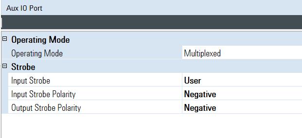
Signal IO Node and Global AUX IO Settings – AUX Input Parameters
This section describes the Signal IO node and Global AUX IO Settings, as they relate to the AUX I/O port input signals. The following AUX port settings are displayed in Figure 1 and Figure 2. For more information, refer to Signal IO.
| Aux Port General Settings |
| State |
On or Off -- Off means the AUX signaling is ignored
|
| Data Polarity |
Positive or Negative -- Positive means a 3.3-volt signal is interpreted as a ‘1’ and a 0-volt signal is a ‘0’. Negative selection inverts this so that a 3.3-volt signal is interpreted as ‘0’ and 0-volt signal is interpreted as ‘1’. |
| Multiplexed Mode Setup
|
|
In the System > Global AUX IO Controls > Operating Mode can be selected as Multiplexed or Dedicated -- in this case it is selected as Multiplexed. Refer to Figure 2 or to the PXB Online Documentation.
|
| First Address |
For the PXB, assign a different Group address for each baseband card. |
| Second Address |
For the PXB, assign a different Group address for each baseband card. |
Dedicated Mode Setup
|
- When Dedicated mode is selected, these fields are used to select the AUX port pin and baud rate of the dedicated connection.
- You can switch between AUX port modes Dedicated and Multiplexed by selecting on the tool bar: System > Global AUX IO Controls > Operating Mode, or by using a SCPI command. Refer to Figure 2 or to the PXB Online Documentation.
|
| Aux Port Pin |
Because the AUX port mode is selected as Multiplexed these settings are not active, and are shown in gray text. When Dedicated mode is selected, this field is used to select the AUX pin of the dedicated connection. |
| Baud Rate |
Because the AUX port mode is selected as Multiplexed these settings are not active, and are shown in gray text. When Dedicated mode is selected, this field is used to select the baud rate of the dedicated connection. |
| AUX Pin/Bit Select |
| Type of Feedback |
Sets the bit location of the feedback command type. This parameter is not available when in multiplexed mode. |
| Timing Adjustment Data |
Sets the bit position of the timing adjustment feedback. This parameter is not available when in multiplexed mode. |
| UL-SCH HARQ ACK/NACK Pattern |
Sets the AUX pin of the multiplexed mode for the UL-SCH HARQ ACK/NACK pattern. |
| UL-SCH HARQ ACK/NACK Pattern 2 |
Sets the AUX pin of the multiplexed mode for the UL-SCH HARQ ACK/NACK pattern 2. |
Switching AUX input Port Modes
The AUX port has a Multiplexed mode and a Dedicated mode. In Multiplexed mode, auxiliary signaling is sent using level-sensitive binary signaling (3.3V LV TTL) connected to one or more AUX port input bits. In Dedicated mode, auxiliary signaling is sent using an RS232C like serial signal at a specified baud rate to a selected AUX port input bit.
The AUX port mode can be selected in the System > > parameter (see Figure 2), by sending a SCPI command, or by using the instrument's front panel. Refer to the PXB Online Documentation.
AUX Port Global Controls
In the Global AUX IO Settings, there are four AUX Port Global controls.
| Operating Mode |
Select Multiplexed or Dedicated. These functions as described Signal IO Node and Global AUX IO Settings -- AUX Input Parameters. |
| Input Strobe |
There are two selections: Free Run or User. In Free Run mode, the instrument samples the values of the AUX input signals (AUX0 ... AUX11), according to the instruments internal timing -- this happens at about 3.5 MHz. In User mode, you must supply a strobe signal which causes the AUX input signals to be sampled. |
| Input Strobe Polarity |
You can choose Positive or Negative polarity. With positive polarity, the AUX input signals are sampled via the rising edge (0V to 3.3V transition) of a pulse (AUX strobe) supplied by you to the AUX I/O connector pin 6. With a negative polarity the AUX input signals are sampled on the falling edge of AUX strobe. |
| Output Strobe Polarity |
Determines when the AUX input signals have been sampled by looking at the AUX sample clock (connector pin 29) signal. If the Output Strobe Polarity is positive, this will be a positive going pulse (about 200 ns pulse width), which is triggered when the AUX input signals are sampled. If the polarity is negative, the AUX sample clock will be a series of negative going pulses about 200 ns pulse width.
|
Operational Signaling Modes
AUX I/O Port: Input Signaling
The Auxiliary I/O port is designed to support your real-time signal generation software configuration with the instrument, and to interface with different configurations of external equipment under test.
For example, consider a sample configuration where you are using LTE TDD uplink signal generation software to control the instrument. The N7625B software can be configured to accept a timing adjustment command and/or HARQ command from external equipment to enable testing of power control loops in base stations.
Auxiliary signaling can be delivered from external equipment in one of two formats.
For a summary of the current channel's Operating Mode (Multiplexed or Dedicated) refer to the PXB's Block Diagram > AUX IO Summary tab. Refer to the PXB's Online Documentation.
- A low-voltage, TTL format where, your equipment uses a binary signal connected to the AUX port in an LV TTL format with 0-volts representing a ‘0’, 3.3-volts representing a ‘1’.
|
|
If this signal cannot be delivered directly from the external equipment, an inexpensive interface board can be used to connect to external equipment with a USB connection, for example the USB Bit Whacker (SKU: DEV-00762, www.sparkfun.com), can be used to interface from your external equipment with a USB connection to the Keysight Auxiliary I/O port.
|
- A serial format where, your equipment uses a serial-port connection, with an LV TTL RS-232 type protocol. Baud rates from 9600 to 460800 are supported in this format. For this purpose, a device can use any low voltage transistor to transistor logic (LV TTL) line that can generate RS-232 type signals, or some simple USB to RS-232 TTL signaling devices can be used.
The default serial format Positive is illustrated in Figures 3 and 4. Each signaling transmission consists of an 8-bit character (bits b7 b6 b5 b4 b3 b2 b1 b0, b0 is least-significant bit, b7 is most significant bit). The signaling transmission consists of a start bit ‘0’, followed by the 8 data bits (transmitted LSB first) followed by a stop bit ‘1’. The bit rate can be one of 9600, 19200, 38400, 57600, 115200, 230400, or 460800 bits per second.
If the polarity is selected as Negative (inverted), then the expected signal will be the inverted form shown in Figure 5.
Figure 3. Serial Data Transmission Format–Polarity is Positive (Default)
Figure 4. Polarity is Positive - Hex Example
Figure 5. Serial Data Transmission Format–Polarity is Inverted
AUX I/O Port: External Device Signaling (Example)
Again, using the LTE TDD example in AUX I/O Port: Input Signaling. In this example, the instrument's LTE TDD can accept HARQ ACK/NACK feedback and or Timing Adjustment feedback. Figure 6 shows a typical interconnect diagram with an LTE TDD base station for purposes of doing base station receiver test. In this example:
- The instrument's RF signal is connected to the input of the base station.
- A frame pulse trigger signal is sent from the base station to the instrument PAT TRIG input (BNC rear panel connector), which enables the instrument to synchronize its frame timing with the base station.
- And, a HARQ and Timing Adjustment feedback signal command is sent to the AUX I/O port (rear panel) of the instrument.
Figure 6. LTE TDD Base Station Receiver Testing Connections (PXB connections to the RF upconverter are not shown)
The availability of HARQ and timing advance (TA) functions are depending on the AUX operating mode (i.e. Dedicated or Multiplexed). In the Multiplexed mode, HARQ ACK/NACK feedback is functional. In the Dedicated mode, HARQ ACK/NACK feedback and Timing Adjustment feedback are functional. In both modes, the external device must provide the signal for every subframe.
The single line's signaling format can be selected as Multiplexed or Dedicated. The instrument's interface enables selection of the signaling format by clicking the following on the tool bar:
> > > or
- In the case of mode, the external equipment can send a 3.3-volt signal or 0-volt signal with each frame to communicate a command to ACK or NACK for a subframe. Timing Adjustment is not available in the Multiplexed mode.
- In the case of mode, the external equipment can send one or two a single characters each subframe to indicate a command to ACK/NACK command or timing advance (TA) command with a feedback type indicator for a subframe. In Dedicated mode, your external equipment sends one or two serial characters for each subframe.
The instrument's AUX pins, AUX0 to AUX11, are available for delivering auxiliary commands from 1- to 12-bits in width in Multiplexed mode.
In Dedicated mode, where serial format signaling is used, serial signaling can be connected to any one of the pins AUX0 to AUX11.
Dedicated Mode
In Dedicated mode, all signaling is delivered in the serial format as in AUX I/O Port:Input Signaling. Serial command signals can be connected to the AUX0 to AUX11 pins of the AUX I/O connector. The serial format transmits 8-bits at a time to the instrument. These bits can be mapped to the auxiliary signaling functions of Signal Studio's real-time signal generation software.
For the LTE TDD HARQ and timing advance (TA) commands, bit7 and bit6 are always assigned to the “Type of feedback” signal. If the signal is “00”, bit5 to bit0 are recognized as a TA command. If bit7 and 6 are “01”, bit1 to bit0 are recognized as a HARQ ACK/NACK command. See Figure 7.
Figure 7. Dedicated Format Transmits 8 Serial Bits
The HARQ command has 2-bits, the upper bit is a reserved bit, and the lower bit represents ACK(1) or NACK(0).
The timing advance(TA) command has 6-bits, the value range is 0 to 63, which is defined as TA, in the 3GPP STD TS36.213 4.2.3 Transmission timing adjustments section.
Multiplexed Mode
In Multiplexed mode, auxiliary commands are delivered as 1- to 12-bit wide commands in LV TTL format.
For the LTE TDD HARQ command, you can select the signal line as AUX0 to AUX11.
Related Topics
Agilent N5106A PXB Baseband Generator and Channel Emulator