Waveform Setup
Save to 89600 Setup File
Activates a dialog to specify the Subframe Offset and Subframe Length to be included into VSA setup.
The Subframe Offset and Subframe Length should fall into the partially generated subframes as defined by Generated Subframe Offset and Number of Generated Subframes.
See the 89600 Setup File Setting section for more information.
Save to xSA Setup File
This feature saves the current waveform configuration to an .xml file, enabling you to quickly configure an X-Series Signal Analyzer to demodulate the signal.
Antenna Port Presets
Choices: Preset to AP0 | Preset to AP1
Used if you want to have quick configuration for MIMO test.
The table below shows the antenna ports for each channel when you click Preset to AP0/AP1.
|
Subframe Configuration |
AP0 |
AP1 | Comments |
|---|---|---|---|
|
xPBCH |
0 |
1 | |
| BRS | 0 | 1 | |
| ePBCH | 500 | 501 | |
| CSI-RS | 16 | 24 | |
| BRRS | 600 | 601 | |
| xPDCCH | 107 | 109 | |
| xPDSCH | 8 | 8 | Single antenna port |
| 8 | 12 | Transmit Diversity or Spatial Multiplexing, OCC = On | |
| 8 | 9 | Transmit Diversity or Spatial Multiplexing, OCC = Off | |
|
xPDSCH PCRS |
60 | 61 | |
| xPUCCH | 100 | 100 | Single antenna port |
| 200 | 201 | Transmit Diversity | |
| xPUSCH | 40 | 40 | Single antenna port |
| 40 | 41 | Transmit Diversity or Spatial Multiplexing | |
| SRS | 40 | 40 | Nap = 1 |
| 40 | 41 | Nap = 2 | |
| xPRACH | 1000 | 1000 |
Add Carrier
Click the Add button to add a new pre-5G carrier to the list. New carrier will be assigned with a different Cell ID based on current carrier count.
Max carrier number is 8.
Delete Carrier
Click the Delete button to delete the selected pre-5G carrier from the list.
Copy Carrier
Click the Copy button to copy the selected pre-5G carrier and append it to the list.
Auto Frequency Offset
Auto adjust the frequency offset of each pre-5G carrier to make them have 99M channel spacing.
99M channel spacing refers to V5G test plan.
Quick Setup -> 8CC
Preset the waveform setup to 8 component carriers with 99M channel spacing.
Cell IDs are different for carriers.
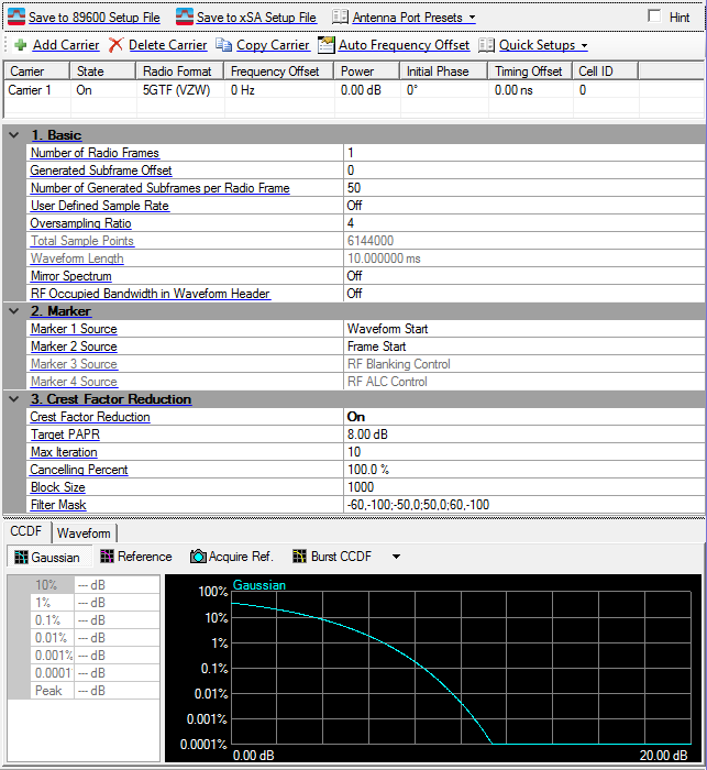
1. Basic
Number of Radio Frames
Default: 1
Enter the number of frames included in the waveform.
The max value is determined by the total waveform length which should be less than 2G samples.
Generated Subframe Offset
Range: 0 - 49
Default: 0
Enter the subframe offset into a radio frame where to start generating the waveform.
Number of Generated Subframes per Radio Frame
Range: 1 - 50
Default: 1
Enter the number of subframes to be generated in a radio frame from subframe offset.
Used for partial generation that is only selected subframes are generated into a radio frame.
Subframe Offset + Number of Generated Subframes <= 50
User Defined Sample Rate
Choices: On | Off
Default: Off
Enable or disable the User Defined Sample Rate. If enabled, the OverSamplingRatio will not be used.
Sample Rate
Range: 100 MHz ~ 4 GHz
Default: 200 MHz
Set the value of user defined sample rate if user defined sample rate is enabled.
Oversampling Ratio
Range: 1 - 64
Default: 4
Enter the oversampling ratio of the waveform. The Total Sample Points is automatically determined based on the oversampling ratio.
Total Sample Points
Displays the generated waveform length in sample points. This value is read-only and automatically updates with changes to oversampling ratio, number of frames, and custom modulation type.
Waveform Length
Displays the generated waveform length in seconds. This value is read-only and automatically updates with changes to oversampling ratio, number of frames, and custom modulation type.
Mirror Spectrum
Choices: On | Off
Default: Off
Enable or disable the mirror spectrum (inverted IQ) for the waveform.
RF Occupied Bandwidth in Waveform Header
Choices: On | Off
Default: Off
Enable or disable RF Occupied Bandwidth field in the waveform header.
2. Marker
Marker 1 Source
Choices: Waveform Start | Frame Start | RF Blanking Control | RF ALC Control
Default: Waveform Start
Select the source for marker 1.
-
Waveform Start: It indicates the beginning of the waveform.
-
Frame Start: It indicates the beginning of each frame in the waveform.
-
RF Blanking Control: It indicates the burst part in the waveform.
-
RF ALC Control: It indicates the part used for ALC control in the waveform.
Marker 2 Source
Choices: Waveform Start | Frame Start | RF Blanking Control | RF ALC Control
Default: Frame Start
Select the source for marker 2.
-
Waveform Start: It indicates the beginning of the waveform.
-
Frame Start: It indicates the beginning of each frame in the waveform.
-
RF Blanking Control: It indicates the burst part in the waveform.
-
RF ALC Control: It indicates the part used for ALC control in the waveform.
Marker 3 Source
Default: RF Blanking Control
Displays the source for marker 3. RF Blanking Control is always used as Marker 3 source.
Marker 4 Source
Default: RF ALC Control
Displays the source for marker 4. RF ALC Control is always used as Marker 4 source.
3. Crest Factor Reduction
Crest Factor Reduction
Choices: On | Off
Default: Off
Enable or disable the crest factor reduction for the waveform. When enabled, peak cancellation algorithm is used to subtract a weighted version of the cancellation pulses from the original input signal. It strikes a balance between the out-of-band emission and in-band waveform quality when reducing the PAPR of the signal.
Crest Factor Reduction is always visible and configurable under Waveform Setup, however, supporting parameters appear only when Crest Factor Reduction is enabled. If the waveform.
PAPR is already lower than the target level, then no processing will be performed on the original waveform.
Target PAPR
Range: 3 - 100 dB
Default: 8 dB
Set the PAPR value to achieve after crest factor reduction.
Max Iteration
Range: 1 - 100
Default: 10
Specify the maximum times of iteration.With the increasing of iteration, the PAPR value should converge to a steady level.
Cancelling Percent
Range: 0 - 100%
Default: 100%
Specify the percentage that the cancellation pulses can be removed.
Block Size
Range: 20 - Waveform Total Sample Points
Default: 1000
Block is the range that a single cancellation pulse can be identified. If the waveform length is L, and the block size is B, then the number of blocks is N=floor(L/B)+1. Therefore, there will be N pulses at most to be removed.
Filter Mask
Bring up the filter mask editor to define a filter response in frequency domain. In the table, the frequency points must be entered with an order of increasing frequency in unit of MHz, and its corresponding amplitude is in unit of dB. When generating this filter mask, the frequency points between the specified points are linearly interpolated. When carrier number or carrier frequency offset in the waveform is changed, this table will be automatically updated. User may need to adjust the mask manually to fit the actual signal bandwidth.
Graph View
The graph view displays several different representations of the generated waveform. For more information, see Graph View.