5G NR Uplink
Click in the tree view to display the 5G NR Uplink pane shown below. The 5G NR Uplink setup pane is divided into two sections: instrument control buttons (top) and Basic properties.
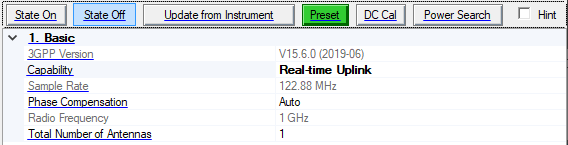
State On
Turns the application on, generating the real-time IQ signal in the connected instrument with the parameters you set in the software.
[:SOURce]:RADio:NR5G[:BBG][:STATe] ON|OFF|1|0
[:SOURce]:RADio:NR5G[:BBG][:STATe]?
State Off
Turns the application off, disabling the real-time IQ and RF signals on the connected instrument.
[:SOURce]:RADio:NR5G[:BBG][:STATe] ON|OFF|1|0
[:SOURce]:RADio:NR5G[:BBG][:STATe]?
Update from Instrument
Click this button to retrieve the parameters from the connected instrument.
Preset
Click this button to set the signal generator to a factory-defined or user-defined state.
Refer to the signal generator's user's guide for information on setting a user-defined state.
:SYSTem:PRESet
*RST
DC Cal
Click the DC Cal button to execute an I/Q DC calibration to minimize errors associated with offset voltages.
DC Cal minimizes I/Q offset errors for a single frequency only and must be repeated if the signal generator's settings change.
Download a waveform to set the correct parameters for the target instrument and activate this button.
You can set this calibration to occur automatically. See Perform DC I/Q Calibration.
:CALibration:IQ:DC
*OPC
Power Search
Set ALC to Off to activate this button.
Click the Power Search button to execute a manual power search calibration. This is an internal calibration routine that improves output power accuracy when the ALC is turned off. A power search is recommended for pulse-modulated signals with pulse-widths less than two microseconds.
Download a waveform to set the correct parameters for the target instrument.
[:SOURce]:POWer:ALC:SEARch ONCE
*OPC
1. Basic
3GPP Version
Default (fixed): V16.2.0 (2020-06)
This read-only field display the supported version of 3GPP specifications:
TS 38.211 Physical Channels and Modulation
TS 38.212 Multiplexing and Channel Coding
TS 38.213 Physical Layer Procedures for Control
TS 38.214 Physical Layer Procedures for Data
Capability
Choice: Waveform Playback | Real-time Uplink
Default: Waveform Playback
Select the capability of 5G signal simulation.
-
Waveform Playback mode means Signal Studio will generate the IQ waveform, using the PC, and then download it to instrument.
Upon selecting this mode, the 5G NR Uplink node in the tree view changes to Waveform Setup and many more parameters appear. Additionally, multicarrier editing buttons appear above the parameters pane, replacing the instrument control buttons.
-
Real-time Uplink mode means the IQ waveform is generated inside the instrument. It can receive HARQ feedback from AUX port for loop back test.
Upon selecting this mode, the Waveform Setup node in the tree view changes to 5G NR Uplink and only the Basic property table is displayed with a subset of parameters. Additionally, instrument control buttons appear above the parameters pane, replacing the multicarrier editing buttons.
Sample Rate
Range: 20 MHz to 12 GHz
Default: 122.88 MHz (61.44 MHz if numerology = 15 kHz)
This parameter is read-only. The sample rate is automatically calculated to meet the requirement of waveform settings and connected instrument.
Phase Compensation
Choices: Auto | Manual | Off
Default: Auto
Set the phase compensation mode on the baseband signal before upconversion.
-
Auto: Use the RF frequency from the instrument node.
-
Manual: Enter the RF frequency manually.
-
Off: Disable phase compensation on baseband signal.
Radio Frequency
Range: 0 to 100 GHz
Default: 1 GHz
Set the Radio Frequency when doing the phase compensation on baseband signal, it is automatically coupled with the frequency of instrument when Phase Compensation is set to Auto, and can be edited when Phase Compensation is set to Manual, but not visible when Phase Compensation is Off.
Total Number of Antennas
Choices: 1 | 2
Default: 1
Set the number of antennas for each generation, it is used for MIMO configuration, there is a parameter called 'Antenna Port(s) Generated' for DL-SCH/ULSCH/CSI-RS/SRS to configure the mapping between antenna and logical antenna port.