This feature is a licenced feature which requires the subscription.
Add Switch Matrix… - select to open the External Device Configuration dialog, user can configure a new switch matrix
<User Config Name> – existing configurations that user can select.
None – when first open this application, “None” is display to indicate switch matrix is not selected. “None” will always appear in the pulldown as a valid selection. If “None” is selected, all other controls on this tab will be gray-out.
Characterize - Open Characterize Switch Matrix wizard
VNA Port n to Test Port – Select test ports. Note: the path will not be switched until clicking the “Switch” button, in order to save the switch matrix service life.
By Test Port - Fill in the test port combo-boxes by port numbers or port labels
Switch – Do switching path
Switch Path - Open Switch Path dialog.
TDR state is on top of VNA state. So, “.tdr” file includes:
“VNA state file” items as in Save_Load.
Selected switch matrix configuration name
L8990M-0LZ is the model number of custom switch matrix for HSD cable compliance test solution. A pre-defined switch profile file will be distributed along with VNA FW installation, user may find it at “C:\Program Files\Keysight\Network Analyzer\DocumentsTemplate\Drivers\L8990M_0LZ_SwitchMatrix.swp”.
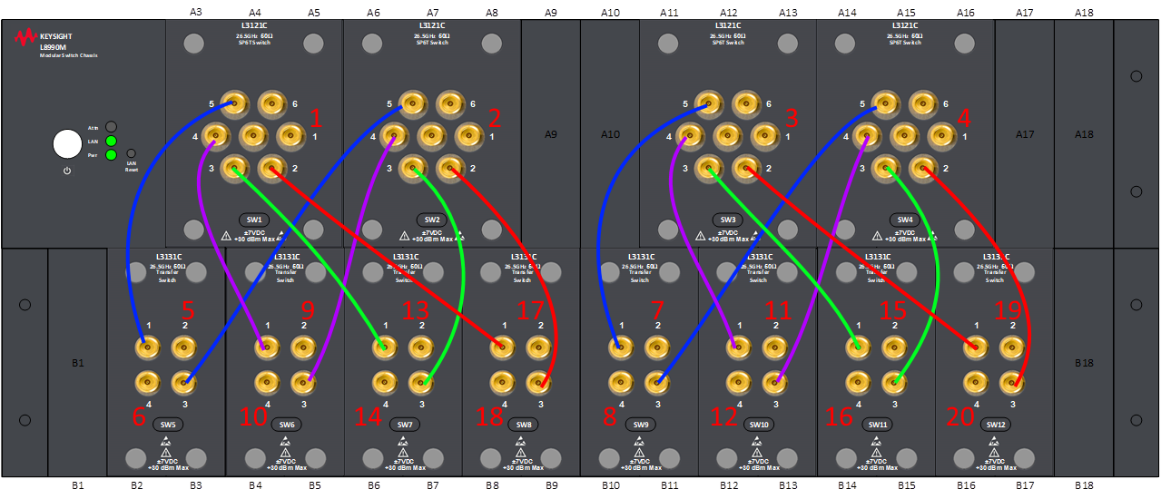
· 4U Frame
· 4x SP6T, 8x transfer switches, 16x semi-rigid cables for connecting switch module to module
In the “External Switch Matrix” properties dialog, switch matrix configuration follow the physical configuration, which is illustrated as below:
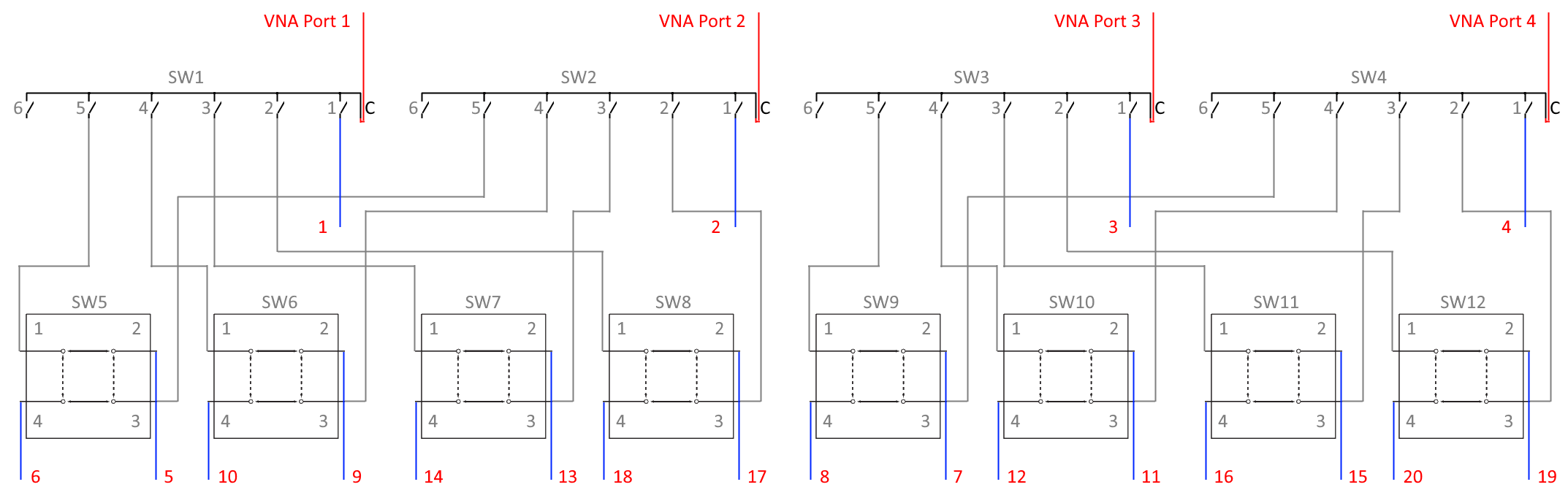
· 16 gray cables
o Semi-rigid cables dedicate to switch-to-switch connections, which are also illustrated in section above (physical configuration)
· 4 red cables
o VNA ports connect to the 4x SP6T Com ports.
· 20 blue cables
o These are test port cables. So, this is a 20-port test system.