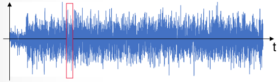
Original (Parent) Waveform
Note: The first line of a modulation file must be the sample rate. In addition, never use a comma within a text comment. Commas are used as data separators only.
Keysight Signal Studio Waveform (.wfm)
Use a .wfm file, which is created using the Keysight Signal Studio Software.
In order to use a compact file (.mdx) which is created from .wfm, the corresponding license is required on the Signal Generator to play the .mdx.
When the waveform pack license is used, the original waveform file must be assigned / locked to the signal generator in order to use the .mdx created from the original waveform file.
Note: Encrypted .wfm files created using the N5182B MXG RF Vector Signal Generator are not supported.
IQ file (.csv)
Use a .csv file format that has a timestamp, I, and Q that uses a comma to separate the values.
No license is required on the signal generator to play the .mdx created from the .csv.
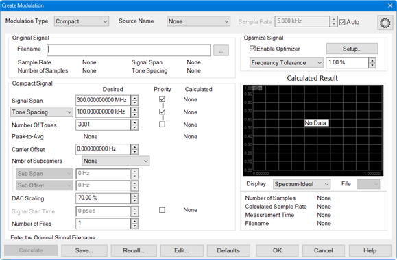
Modulation Type - Selects the modulation type (note that these define signals, not measurements):
Digital Mod - Creates an I/Q modulation waveform.
Compact - Compact signals cut a slice of the IQ data from an original waveform.
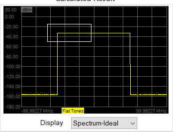
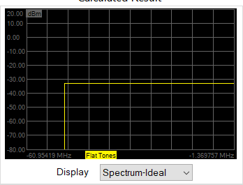
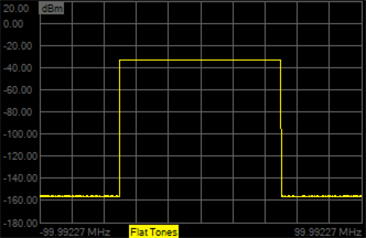
Flat Tones - This signal is a set of constant amplitude tones over a defined signal span.
NPR Notch - This signal is a set of constant amplitude tones over a defined signal span where a subset of those tones are set to zero over a notch span.
Digital Modulation Type
Note: Create Digital Modulation is a Licensed Feature and only available on PNA/PNA-X instruments. Learn more about Licensed Features.
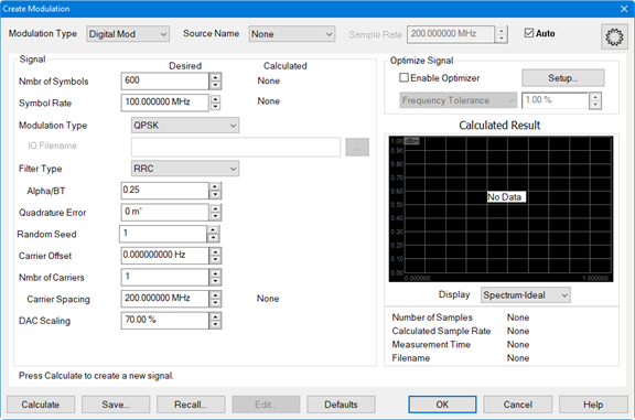
Source Name - Selects the modulation source. Learn more.
Sample Rate - Sets the source sample rate.
Auto - Automatically selects a sample rate for the active source depending on the modulation requested. If the modulation is invalid (for example, 0 Hz span), then Auto will default the sample rate to 100 MHz.
Nmbr of Symbols - Specifies the number of symbols in the waveform.
Symbol Rate - Specifies the rate, or frequency, at which symbols occur.
Modulation Type - Selects a modulation type:
QPSK
8-PSK
16-QAM
64-QAM
256-QAM
1024-QAM
BPSK
8-APSK
16-APSK CR 9/10
32-APSK CR 9/10
IQ File - If selected, enter a filename of an existing IQ file in the field.
IQ Filename - If Modulation Type is set to IQ File, then this file defines the IQ constellation. The symbols will be pseudo-randomly chosen from these constellation values. The file is a *.csv with the following format:
I_1,Q_1
I_2,Q_2
I_3,Q_3
...
I_N,Q_N
Filter Type - Specifies the filter to apply to the time data.
Alpha/BT - Selects the Alpha/BT characteristics of the selected filter.
Quadrature Error - Indicates the orthogonal error between the I and Q signals. The ideal orthogonal between I and Q signals is 90 degrees. An error of 3 degrees indicates that the I and Q are 93 degrees apart.
Random Seed - The waveform is created using a pseudo-random number generator. The number generator starts at a value determined by the Random Seed. For a given Random Seed, the number generator will always create the same pseudo-random sequence of values. Changing the Random Seed will change the pseudo-random sequence. The Random Seed may be set to an integer between 1 and 1,000,000.
Carrier Offset - Sets the carrier offset value relative to the carrier LO frequency.
Nmbr of Carriers - Allows selection of multiple carriers for multi-carrier modulated signals. The default is 1.
Carrier Spacing - Specifies the space between carriers when setting up multi-carrier signals.
DAC Scaling - Sets the scaling factor used for the waveform (full scale = 100%). This ensures that the DAC filter does not output a signal that is larger than the DAC's maximum output level, which can cause distortion in the system. Setting the scaling factor to 100% will usually cause excessive distortion.
Calculated - Displays the settings that were used to create the modulated signal.
Enable Optimizer - When enabled, the calculated modulated signal will be optimized according to the constraints defined in this group box.
If Enable Optimizer is disabled:
-
Always creates a signal that can be measured by the PNA.
-
If the Priority box for Waveform Period or Tone Spacing is checked, then this will attempt to create the exact desired period if possible.
-
If the Priority box for Number of Tones is checked, then this will attempt to create the exact desired number of tones if possible.
-
In some cases, the resulting file will be too large, or the frequencies will be inconsistent with the ADC frequencies. In these cases, the desired values will not be used.
Setup... button - Accesses the Optimizer Setup dialog.
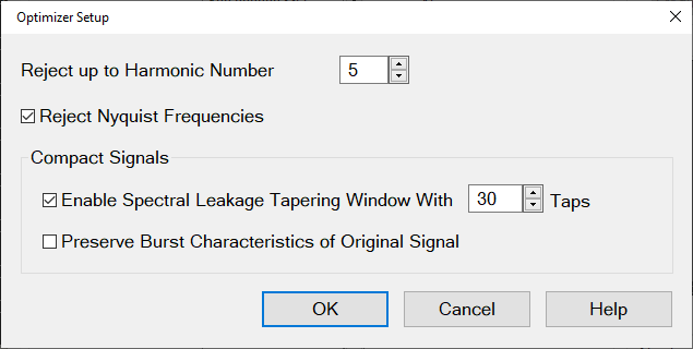
Note: These settings only apply if "Enable Optimizer" has been selected in the "Create Modulation" dialog.
Reject up to Harmonic Number - Rejects images up to the defined harmonic number.
Default: 5
Minimum value is 1, which rejects the first image at negative frequency.
More rejection requires longer measurement time to create longer filters having more nulls to cancel the images.
Reject Nyquist Frequencies - The PNA 38-MHz anti-alias filter has poor Nyquist rejection. This should be enabled when using that AAF. This is not true for the 11MHz AAF in the PNA, or for any other AAF filters in other platforms.
Default: ON
Selecting this ensures that the tone spacing is not equal to Fadc/N, where Fadc is the ADC clock frequency. Avoiding these tone spacings will allow the filter to null the 2nd Nyquist leakage.
Compact Signals:
Enable Spectral Leakage Tapering WIndow With [n] Taps - This is only applied to Compact Signals.
Defaults: ON, Taps = 30.
The Compact Signal is generated from a time slice of the Original Signal. This time slice is repeated. The Tapering Window is used to smooth the ends of the time slice to minimize spectral splatter caused by a sharp transition at the boundary. If you have enabled "Pteserve Burst Characteristics of Original Signal", then the Tapering Window is used to smooth the edges of the burst to avoid spectral splatter..
Preserve Burst Characteristics of Original Signal - This is only applied to Compact Signals.
Default: OFF
If turned ON, then the code will determine if the Original Signal is a Burst Signal and ensure that the Compact Signal will be a burst with the same duty cycle.
Optimize Signal pull-down menu:
Frequency Tolerance - Set the allowed tolerance for tone spacing when calculating the modulation signal. Wider tolerance results in selection of tone spacing which require smaller files and less measurement time. If the tolerance to too small to provide a solution, then a solution is calculated with the minimum possible tolerance and the tolerance value will be changed.
Min Waveform Period - Minimizes the period of the waveform greater than or equal to the value (seconds).
Min Number of Tones - Minimizes the number of tones greater than or equal to the value. This will ignore the Number of Tones selection.
Max Tone Spacing - Maximizes the tone spacing less than or equal to the value (Hz). This will ignore the Tone Spacing selection.
Display - Select from the following:
Spectrum-Ideal - Displays the spectrum represented by floating point numbers, which results in a very low noise floor.
Spectrum-16bit - Displays the spectrum represented by 16-bit numbers, which results in more distortion.
Time - Displays the signal in the time domain.
CCDF - Displays the complementary cumulative distribution function.
CCDF Error - (Compact Modulation Type only) Displays the difference between the parent signal and created signal. The Y-axis is displayed in linear %.
Number of Samples - Displays the calculated file size. If there are no calculated results, None is displayed.
Calculated Sample Rate - Displays the calculated sample rate. If there are no calculated results, None is displayed.
Measurement Time - Displays the minimum measurement time for the calculated signal. If there are no calculated results, None is displayed.
Filename - Displays the name of the modulation file. If the calculated result has not been saved, None is displayed.
Click-and-drag over a part of the display to zoom in on data.
Right-click in the display area to access the following menu:
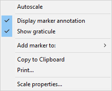
Autoscale - Automatically scales the data to fit vertically within the display grid area.
Display marker annotation - Select to display marker annotation in the top-right of the display.
Show graticule - Select to display graticules.
Add marker to: - Select to add a marker to the displayed data trace. When a selection is made, the mouse pointer changes to a "+". Click in the display area and the marker will appear. Drag the marker to the desired position. Each time this selection is made, a new marker will be added to the data.
Choose from:
Original/Compact - Add marker to the original data and/or the calculated compact data when the Modulation Type selection is Compact.
Flat Tones - Add marker to flat tone data when the Modulation Type selection is Flat Tones.
NPR Notch - Add marker to notch data when the Modulation Type selection is NPR Notch.
Copy to Clipboard - Copies a bitmap of the trace control (Display) to the clipboard. It can then be pasted into any document that accepts bitmaps.
Print... - Prints the displayed data.
Scale properties... - Accesses the following dialog:
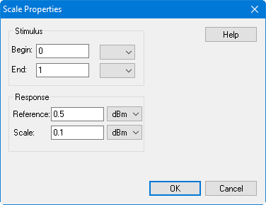
Stimulus - Sets the Begin and End frequency displayed on the X-axis.
Response - Sets the Reference level in the center of the Y-axis and sets the scale per division.
Compact Modulation Type
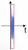
Compact signals cut a slice of the IQ data from an original waveform. The slice of IQ data is chosen that best fits in terms of statistical distribution (CCDF), then conditions the waveform so that it has the same spectrum signature as the original signal.
Original signal:
Compact signal:
Source Name - See above.
Sample Rate - See above.
Filename - Select the filename of the original (parent) modulation file to be compacted.
Sample Rate - Displays the sample rate of the original modulation file.
Number of Samples - Displays the number of samples in the original modulation file.
Tone Spacing - Displays the tone spacing of the original modulation file.
Waveform Period - Displays the waveform period of the original modulation file.
Signal Span - Displays the signal span value of the original modulation file.
Carrier Offset - Displays the carrier offset value of the original modulation file.
Signal Span - Sets the frequency span of the modulated carrier.
Tone Spacing/Waveform Period - Sets the desired tone spacing or waveform period and shows the calculated tone spacing or waveform period.
Number of Tones - Sets the desired number of tones. This setting is related to the span and tone spacing: (Number of Tones) = (Signal Span)/(Tone Spacing) +1.
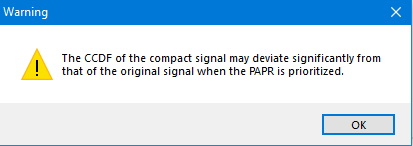
PAPR (continuous) - Displays the peak-to-average value of the continuous signal rather than the sampled signal. When checking the Priority box, the compact signal will include the maximum peak of the original signal.
By default this is OFF. Setting this as a priority may cause problems with the signal statistics; a warning dialog shown below will be displayed if this checkbox is selected.
Carrier Offset - See above.
DAC Scaling - See above.
Signal Start Time - Sets where to start the compact signal within the original signal. The compact signal is a slice of the original signal.
Note: The Priority checkbox must be checked to use this value.
Number of Files - Sets the number of modulation files to create. This function is useful to create several signals, compare them, then save the best signal.
Priority - Check to attempt to calculate values closer to the desired values.
Calculated - See above.
Enable Optimizer - See above.
Optimize Signal pull-down menu - See above.
Display - See above.
File - Allows you to switch between multiple created signals for comparison, then save the best signal. Use Number of Files to specify the number of files to create for comparison.
Flat Tones Modulation Type
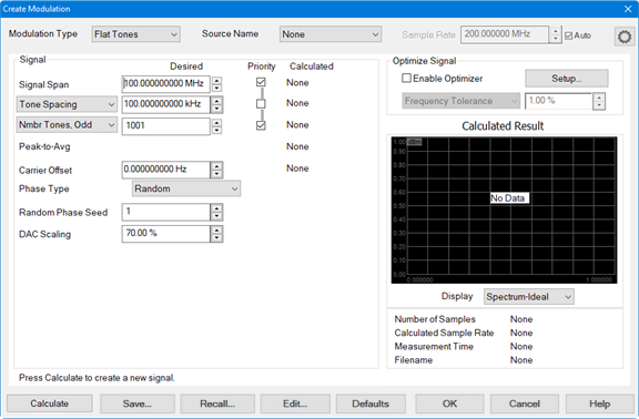
Source Name - See above.
Sample Rate - See above.
Signal Span - See above.
Tone Spacing/Waveform Period - See above.
Number of Tones - Select between odd or even number of tones and sets the desired number of tones. This setting is related to the span and tone spacing: (Number of Tones) = (Signal Span)/(Tone Spacing) +1.
Nmbr Tones, Odd - This forces the optimizer to choose an odd number of tones. The optimizer will also choose an offset such that the carrier lands on one of the tones.
Nmbr Tones, Even - This forces the optimizer to choose an even number of tones. The optimizer will also choose an offset such that the carrier either lands on one of the tones, or exactly halfway between the tones.
Peak-to-Avg - See above.
Carrier Offset - See above.
Phase Type - Select Random, Fixed, or Parabolic.
Random Phase Seed - Sets the phase seed when Random phase is the Phase Type.
DAC Scaling - See above.
Priority - See above.
Calculated - See above.
Enable Optimizer - See above.
Optimize Signal pull-down menu - See above.
Display - See above.
NPR Notch Modulation Type
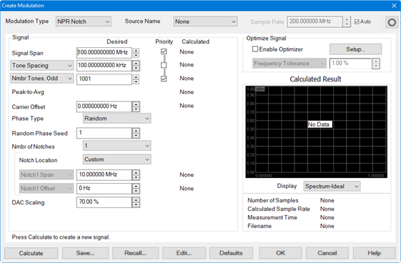
Source Name - See above.
Sample Rate - See above.
Signal Span - See above.
Tone Spacing/Waveform Period - See above.
Number of Tones - See above.
Peak-to-Avg - See above.
Carrier Offset - See above.
Phase Type - See above.
Random Phase Seed - See above.
Nmbr of Notches - Sets the number of notches in the modulated signal.
Notch Location - Select from the following:
Symmetric - Locates the notch in the center of the signal span.
Avoid Carrier - Locates the notch near the center of the signal span but will be shifted to avoid the LO carrier feedthrough.
Custom - Allows the user to define the offset of the notch.
Notch N Span - Sets the span of the selected notch. The notch can be up to 10% of the Signal Span.
Notch N Offset - The offset frequency is the center frequency of the selected notch relative to the LO carrier frequency. Typically, the notch will have a 0 Hz offset, meaning it is centered on the LO carrier. If you have more than one notch, you can offset some of the notches from the carrier. For example, if you have three notches 1 MHz wide, you might set their offsets to -10 MHz, 0 MHz and +10 MHz so that they are spaced across the wideband carrier.
DAC Scaling - See above.
Priority - See above.
Calculated - See above.
Enable Optimizer - See above.
Optimize Signal pull-down menu - See above.
Display - See above.
Buttons
Calculate button- Calculates the result from the current settings. If calculated results exist then data is plotted on the display. If there are no calculated results then there is no plotted data and No Data is displayed. The calculated result is erased if you click on the Defaults button or Recall... button and recall a previously saved file.
Save... button - Saves the current modulation settings.
Recall... button - Recalls a previously saved modulation file.
Edit... button - Accesses the Edit Multitone dialog:
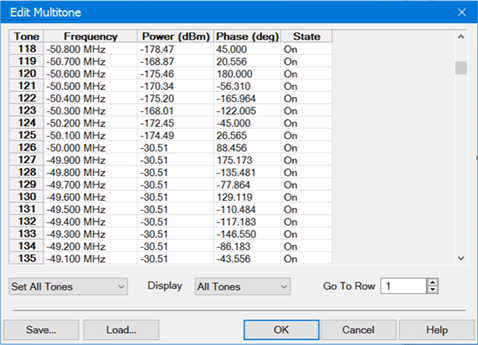
Tone - Tone number from 1 to N. Cannot be edited.
Frequency - Frequency of tone in Hz relative to the carrier. Cannot be edited.
Power (dBm) - Tone power in dBm. Click in the cell to edit.
Phase (deg) - Tone phase in degrees. Click in the cell to edit.
State - Click in the cell to turn the tone on or off.
Set All Tones - Set all tone states to on or off.
Display - Select which tones to display in the table (All Tones, On-Tones, or Off-Tones).
Go To Row - Jumps to the specified row. Enter the row number then press Enter.
Save... button - Saves the current multitone settings as a .csv file.
Load... button - Loads a previously saved multitone .csv file.
Defaults button - Restores default modulation settings for the current Modulation Type.