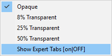
Right-click in a Modulation Distortion dialog.
Select Show Expert Tabs (on|OFF).
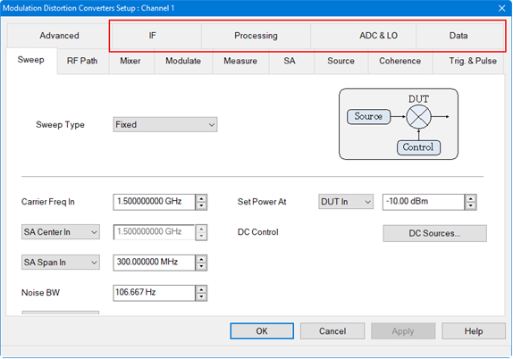
The Modulation Distortion dialog settings are contained within four tabs: Sweep, RF Path, Modulate, and Measure. A fifth tab called Mixer contains settings for converter measurements
For convenience, the Spectrum Analyzer tabs can be displayed as follows:
Right-click in a Modulation Distortion dialog.
Select Show Expert Tabs (on|OFF).
The tabs are displayed next to the Modulation Distortion tabs:

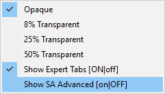
To display the Spectrum Analyzer Advanced tabs, right-click again in a Modulation Distortion dialog then select Show SA Advanced (on|OFF):
The Spectrum Analyzer Advanced tabs are displayed:
In this topic:
X-axis Type (Modulation Distortion/Modulation Distortion Converters only)
Measurement Setup Converters
On the VNA front panel, press Meas > S-Param > Meas Class....
Select Modulation Distortion, then either:
OK delete the existing measurement, or
New Channel to create the measurement in a new channel.
The Modulation Distortion dialog is displayed.
Accessing Modulation Distortion Settings |
|
|
Using Hardkey/SoftTab/Softkey |
Using a mouse |
|
|
On the VNA front panel, press Meas > S-Param > Meas Class....
Select Modulation Distortion Converters, then either:
OK delete the existing measurement, or
New Channel to create the measurement in a new channel.
The Modulation Distortion Mixer Setup dialog is displayed.
Accessing Modulation Distortion Mixer Settings |
|
|
Using Hardkey/SoftTab/Softkey |
Using a mouse |
|
|
|
Fixed and Power Sweep Type Dialogs for Modulation Distortion Measurement Class (MOD)
Fixed and Power Sweep Type Dialogs for Modulation Distortion Converters Measurement Class (MODX)
Fixed - Fixed sweep measures a modulated signal with a fixed carrier LO frequency and power level. Power - Power sweep sweeps the total power of the modulated signal at multiple power levels defined by a start/stop power level. This power may be defined at the input or output of the DUT, depending on the leveling defined in the RF Path tab. The current start/stop power settings are displayed next to the Power Sweep button. Carrier Frequency - (Modulation Distortion only) Sets the carrier LO frequency. The frequency range that can be set is extended to the up-convertor's maximum (M983xA-270) SA Center/SA Start - (Modulation Distortion only) Sets the Spectrum Analyzer display center or start frequency. SA Span/SA Stop - (Modulation Distortion only) Sets the Spectrum Analyzer display span or stop frequency. Note: The SA displayed frequency range is limited to the measurement band frequencies Set Power At - Sets the power level used for the distortion test. The menu provides the following selections: DUT In - Sets the nominal carrier power level at the input port. DUT Out - Sets the nominal carrier power level such that source power + nominal DUT Gain = requested power level. Receiver - a1 - Uses the input port’s reference receiver to level the input power to the desired value. If receiver power corrections are on, the input power will be set at the DUT input reference plane. Rcvr Leveling... - Brings up the Receiver Leveling dialog for more complex setups.
Buttons Power Sweep... button - Accesses the Power Sweep dialog.
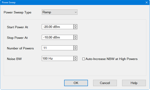
Power Sweep Type - Ramp Ramp - Selects a ramp type power sweep and displays the following information:
Start Power At - Sets the start power value for the power sweep. Stop Power At - Sets the stop power value for the power sweep. Number of Powers - Sets the number of power points to measure. Noise BW - This is the same value as shown in the Sweep tab dialog. Auto-Increase NBW at High Powers - The Noise BW setting will be used for the minimum power level. As the power level increases, the Noise BW will increase automatically. This results in faster measurements and ensures that the noise error is approximately the same for each power level.
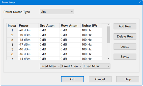
Power Sweep Type - List List - Selects a list of power values to define a power sweep and displays the following information:
Index - Each index entry defines a power level, source and receiver attenuation, and noise bandwidth for the power sweep. Power - Sets the power level for the specific index number. Src Atten - Fixed Atten - Setting one attenuation value in the column sets them all to the same value. Custom - Settings for each index may be different. Note that the Src Atten entry on the RF Path tab will indicate Swept under this condition. Rcvr Atten - Fixed Atten - Setting one attenuation value in the column sets them all to the same value. Custom - Settings for each index may be different. Note that the Rcvr Atten entry on the RF Path tab will indicate Swept under this condition. Noise BW - This is the same value as shown in the Sweep tab dialog if the Noise BW column is set to One NBW or Auto-Increase. Fixed NBW - Setting one noise bandwidth value in the column sets them all to the same value. Custom - Settings for each index may be different. Note that the Noise BW entry on the Sweep tab will indicate Swept under this condition and will be grayed-out. Auto-Increase - The Noise BW setting will be used for the minimum power level. As the power level increases, the Noise BW will increase automatically. This results in faster measurements and ensures that the noise error is approximately the same for each power level. Add Row button - Adds a row after the currently selected row in the table. Delete Row button - Deletes the currently selected row. Load... button - Loads a .csv file into the table. Save... button - Saves the table to a .csv file.
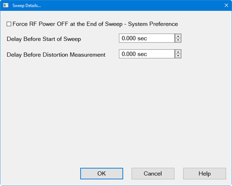
DC Sources... button - Accesses the standard dialog for controlling power supplies. Learn more. Sweep Details... button - Accesses the following dialog: Dialog for Modulation Distortion Converters Measurement Class
Force RF Power OFF at the End of Sweep - System Preference - If enabled, RF power is turned off at the end of a sweep. Note: This setting is a system-wide preference; the state of this setting will affect all measurement channels and the state will not change if the VNA is preset or restarted. Delay Before Start of Sweep - Same as Sweep Delay in a standard channel. Delay Before Distortion Measurement - Adds delay after the linear S-parameter sweep and before the distortion measurement to allow the RF source to settle. Apply button - Applies any changes to the settings in this dialog. |
|
|
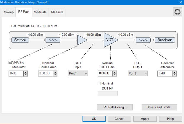
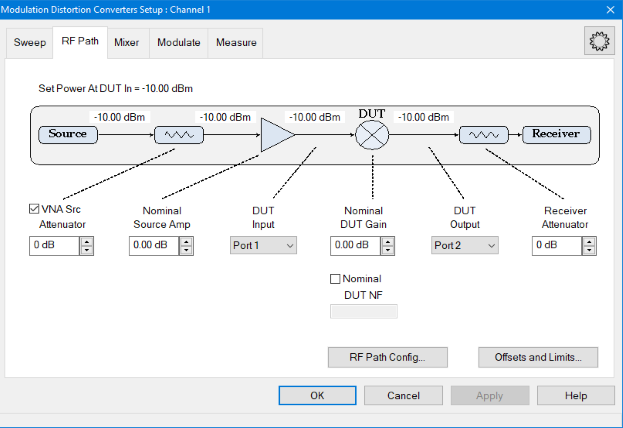
This dialog allows measurement set up on a 2-port DUT. Dialog for Modulation Distortion Measurement Class (MOD)
Dialog for Modulation Distortion Converters Measurement Class (MODX)
Set Power At DUT In - Displays the DUT power set in the Sweep tab. VNA Source Attenuator - Sets the VNA's internal source attenuator Nominal Source Amp - Sets the nominal gain (positive number) from an amplifier or loss (negative number) due to an attenuation, cable loss, etc. This value is used by the Set Power At function, receiver leveling, and calibration. This value is equal to the Power Offset setting found on the Offsets and Limits dialog. Correction ON/Src Amp = - If Source Correction in the Modulate tab is set to Power or Mod & Pwr, then the Correction ON and corrected Src Amp = labels will be displayed below Nominal Source Amp. If power is set at the DUT output, then (Corrected Power Offset) = (Corrected Source Amp) + (Nominal DUT Gain). If power is set at the DUT input, then (Corrected Power Offset) = (Corrected Source Amp). DUT Input - Sets the VNA port number that is connected to the DUT input. Nominal DUT Gain - Sets the nominal DUT gain. This value is used by Set Power At DUT Out, receiver leveling, and calibration. This function is also displayed on the calibration dialog. DUT Output - Sets the VNA port number that is connected to the DUT output. Nominal DUT NF - Sets the nominal DUT noise figure. The default is 0 dB. If checked, the noise will be added back into all measured data after averaging, so that the measured data includes the DUT noise. This value is used by the EVM, ACP and NPR measurement. It will also affect the displayed data and the IQ data which may be exported to the VSA application. Receiver Attenuator - Sets the VNA's internal receiver attenuator for the currently selected output port.
Buttons RF Path Config... button - Accesses the RF Path Configuration dialog. Offsets and Limits... button - Accesses the Offsets and Limits dialog. Apply button - Applies any changes to the settings in this dialog.
|
|
|
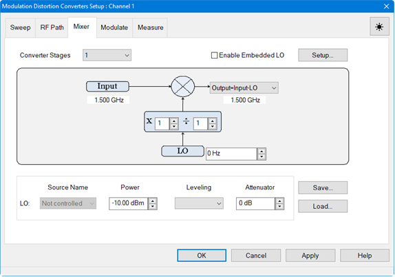
Converter Stages - Selects between 1- or 2-stage mixer configuration. Enable Embedded LO - Check to enable measurements of mixers that have a fixed LO inside the DUT. Note: Embedded LO does not support signals with a tone spacing of less than 1 kHz. Setup... - Opens the Embedded LO dialog.
Enable Embedded LO - Check to enable measurements of mixers that have a fixed LO inside the DUT. Tuning Method - These settings determine the amount of time spent versus the degree of accuracy to which the LO Frequency is measured. Accuracy is compromised when noise starts to appear on the measurement trace. Broadband and Precise Does the entire tuning process for each background sweep. Precise Only Does NOT perform broadband tuning on each sweep. Use this setting when the embedded LO is stable. The signal (after broadband) must be within ½ the tuning IFBW. If the signal will always be within ½ the IFBW, broadband tuning is not needed. Most satellite components are within 3 kHz absolute so might not need broadband tuning. Disable Tuning Only the previously measured LO Frequency Delta is applied to the reference mixer LO and VNA receivers. Tune every - Set the interval at which tuning is performed before a measurement sweep. 'Tune every 3 sweeps' means that every third measurement sweep is preceded by tuning sweeps. If the embedded LO drifts, or if regularly changing DUTs, use 'Tune every 1 sweep'. Broadband Search - Set the frequency span over which to measure the embedded LO frequency. Noise BW - Noise Bandwidth used for Broadband and Precise tuning sweeps. This sets the resolution in the Broadband sweeps. Max Iterations - The maximum number of Precise sweeps to make. When this number is reached, the final measurement is used. Tolerance - When two consecutive Precise measurements are made within this value, the final measurement is used. If this is not achieved within the Max Iterations value, then the last measurement is used. This is the best of the 'Tunings settings' to change to improve accuracy. LO Frequency Delta - The absolute difference between the measured embedded LO frequency and the LO setting that is entered in the Mixer Tab dialog. Find Now - The VNA finds and measures the actual LO frequency using the current dialog settings. This data is displayed in the Status box. Default - Resets the LO Frequency Delta and Tuning parameters to their default settings. Input - Input frequency defined on the Sweep tab. IF - Intermediate frequency between stage 1 and stage 2 for a 2-stage mixer configuration calculated from the mixer equation selection. Choose from the following mixer equations: IF=Input+LO1 IF=Input-LO1 IF=LO1-Input Output - Mixer output frequency calculated from the mixer equation selection. Choose from the following mixer equations for a 1-stage mixer configuration: Output=Input+LO Output=Input-LO Output=LO-Input
Choose from the following mixer equations for a 2-stage mixer configuration: Output=IF+LO2 Output=IF-LO2 Output=LO2-IF X - The combination of numerator / denominator forms a fractional value that is multiplied by the input and LO frequency ranges. Learn more. LO/LO1/LO2 - Sets the LO frequency. Source Name - Select Not Controlled to allow an external source to provide a Fixed LO Frequency at all times. Otherwise, select an internal VNA source or External source to be used as the LO. Learn how to Configure an External Device (Source). Power - Sets the LO power. Leveling Open Loop - No ALC or receiver leveling. No leveling is used in setting the power. Internal - ALC leveling. Power level within an attenuator setting is limited to the ALC range. Attenuator - Selects the receiver attenuation. Save... button - Saves the mixer configuration to a .mxr or .mxrx file. Load... button - Loads an existing mixer configuration file. Apply button - Applies any changes to the settings in this dialog.
|
|
|
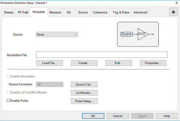
Dialog for Modulation Distortion Measurement Class (MOD)
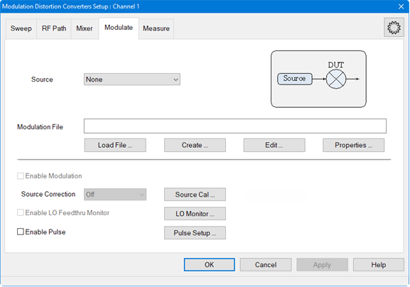
Dialog for Modulation Distortion Converters Measurement Class (MODX)
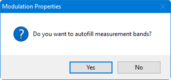
Source - Selects sources that have been defined in the External Device Configuration dialog or selects Source3 (requires Option S93072B, Option XSB, Option S93070xB or Sx090A/B, and either Option 422 or Option 423). Add Source... - Adds a new external source using the External Device Configuration dialog. Source3 - With Option S93072B Arbitrary Waveform Generation on XSB Port (requires Option S93072B, Option XSB, Option S93070xB or Sx090A/B, and either Option 422 or Option 423), an internal third RF source can be selected from the SRC3 connector on the rear panel. Refer to Set Up Source3 Modulation Source - Option S93072B for important setup information. Note: If the source selection is changed, and if a modulation file is selected and Enable Modulation is checked, then the modulation file will be automatically loaded into the source. Modulation File - Displays the currently loaded modulation file. Supported file types include *.mdx, *.csv, and *.wfm. After selecting a modulation file, the following dialog is displayed to allow you to Autofill the measurement bands:
Note: Once a source is selected and a file is selected, the file will be automatically loaded into the source and the Enable Modulation box is checked, Enable Modulation - Check to enable modulation. Off - Do not include power or modulation calibration in source correction. Modulation - Include modulation calibration in source correction. This includes the LO Feedthru correction. Power - Include power calibration in source correction. Mod & Pwr - Include power and modulation calibration in source correction. This includes the LO Feedthru correction. Note: If no correction exists in the modulation file, then the Source Correction selection is grayed-out and disabled. Enable LO Feedthru Monitor - Check to enable LO Feedthru monitor. Enable Pulse - Check to enable standard pulse modulation.
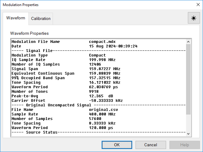
Buttons Load File... button - Loads an existing modulation file. Supported file types include *.mdx, *.csv, and *.wfm. Create... button - Set up a modulation file. See Create Modulation dialog description. Edit... button - Edit the currently loaded modulation file. See Create Modulation dialog description. Waveform Tab Displays the properties of the currently active modulation file, which was selected in the Modulation settings dialog. This information cannot be edited.
Calibration Tab The Calibration tab displays the calibration files and their properties stored in the .mdx file. Each calibration displayed in the list is for one power level. Calibrations may have been performed on multiple power levels during a single calibration. In this case, multiple calibrations will be saved in the .mdx file. Any of these calibrations can be deleted by selecting the calibration name then clicking on the Delete Cal button.
Source Cal... button - Accesses the Modulation Cal - Setup dialog for performing source modulation calibration.
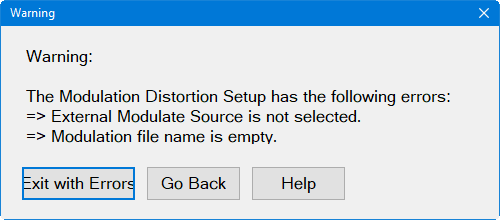
LO Monitor... button - See LO Feedthru Monitor dialog help below. Pulse Setup... button - Opens the Pulse Setup dialog to set up a pulse measurement. When the OK button is clicked, the following warning is displayed if a source has not been added or the Modulation file name has not been specified:
Click Exit with Errors to exit the setup dialogs with the errors or click Go Back to return to the setup dialogs to fix the error. Apply button - Applies any changes to the settings in this dialog.
|
|
|
|
|
| Programming Commands | |
|
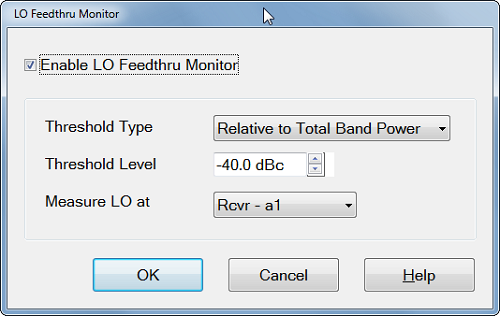
The SA multitone NPR and the Modulation Distortion measurement use a vector signal source. It may have LO feedthrough leakage and the level may drift after calibration due to hardware imperfection. The LO feedthru calibration, as a part of source modulation calibration, reduces the LO feedthru by adjusting I/Q offset voltage. The LO Feedthru Monitor feature notifies you when you should take the calibration again. You need to setup them depends on your measurement requirements.
The firmware checks the LO feedthru level on every measurement. Exceeding the tolerance make a warning message of "LO Feedthru is out of tolerance on channel <n>. Perform Source Modulation Cal > LO Feedthru Calibration". Supported measurements are Modulation Distortion measurements (MOD, MODX) and SA multitone NPR measurement. Non-multitone SA is not supported.
Enable LO Feedthru Monitor - Check to enable LO Feedthru Monitor. LO feedthru level is checked on every measurement. Note: Enable LO Feedthru Monitor is grayed out for internal sources. Threshold Type -
Threshold Level - Set the threshold level. Measure LO at - Select th port to monitor th LO feedthu signal. Select the reference receiver in most cases.
|
|
|
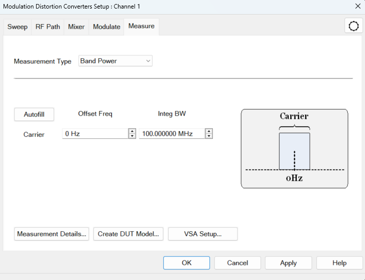
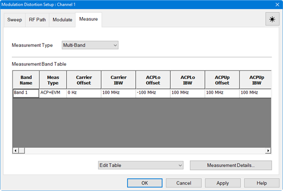
Measurement Type - Selects the measurement type: ACP - Performs ACP measurement. ACP+EVM - Performs both ACP and EVM measurements. Band Power - Measures total power within a specified frequency span. EVM - Performs EVM measurement. NPR - Performs NPR measurement. Multi-Band - Displays the full Measurement Band Table.
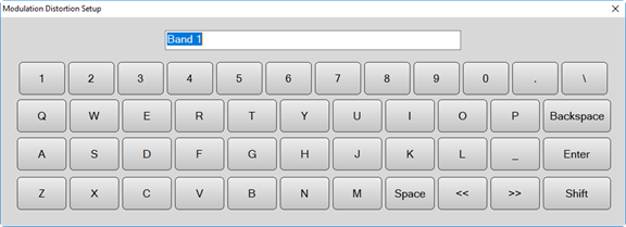
Append Band - Adds a new band after the row with a currently selected active cell. Each band is assigned to a measurement type. Distortion parameters are calculated over the measurement bands. Delete Band - Deletes the row with a currently selected active cell. Edit Band Name - Change the Band Name. Autofill Current Table from Mod File - Attempts to fill all existing NPR bands in the current table. For example, if there are three NPR bands in the table, all three NPR bands are filled according to the notches in the modulation file. Create New Table from Mod File - Clears the current table, then adds the multi-NPR bands. Band Name -Right-click in the Band Name field to display a keyboard for editing the name.
Carrier Offset Freq - Offsets the Carrier integration bandwidth relative to the Carrier LO used to generate the modulation signal. Use the up/down arrows or double-click in the field to display the keypad for entering frequency. Carrier Integ BW - Sets the Carrier integration bandwidth for the distortion measurement. The IBW is used to determine total signal power within a specified frequency span. For example, to calculate the total power of a signal composed of 100 tones spaced 1 MHz apart over a 100 MHz span, the signal power would be integrated over an IBW of 100 MHz. Notch Offset Freq - (NPR measurement only) Sets the notch center relative to the carrier LO used to generate the modulation signal. Use the up/down arrows or double-click in the field to display the keypad for entering frequency. Notch Integ BW - (NPR measurements only) Sets the integration bandwidth of the NPR notch measurement. The IBW is used to determine total signal power within a specified frequency span. For example, to calculate the total power of a notch composed of 100 tones spaced 1 MHz apart over a 100 MHz span, the notch power would be integrated over an IBW of 100 MHz. ACPLo Offset Freq - (ACP measurements only) Offsets the lower ACP integration bandwidth relative to the LO used to generate the modulated signal. Use the up/down arrows or double-click in the field to display the keypad for entering frequency. ACPLo Integ BW - (ACP measurements only) Sets the integration bandwidth of the lower ACP measurement. The IBW is used to determine total signal power within a specified frequency span. For example, to calculate the total power of a signal composed of 100 tones spaced 1 MHz apart over a 100 MHz span, the signal power would be integrated over an IBW of 100 MHz. ACPUp Offset Freq - (ACP measurements only) Offsets the upper ACP integration bandwidth relative to the LO used to generate the modulated signal. Use the up/down arrows or double-click in the field to display the keypad for entering frequency. ACPUp Integ BW - (ACP measurements only) Sets the integration bandwidth of the upper ACP measurement. The IBW is used to determine total signal power within a specified frequency span. For example, to calculate the total power of a signal composed of 100 tones spaced 1 MHz apart over a 100 MHz span, the signal power would be integrated over an IBW of 100 MHz.
Buttons Autofill -Automatically fills in the measurement settings for all bands from the currently active modulation file loaded in the source:
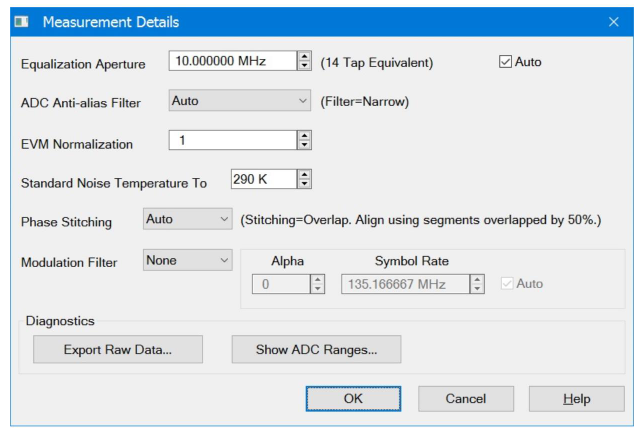
Measurement Details... button - Accesses the Measurement Details dialog:
Equalization Aperture - Sets the frequency span window used for modeling the DUT's gain and distortion. Auto - Check to automatically set Distortion Aperture to window size. ADC Anti-alias Filter - Selects between auto and wide IF filter anti-aliasing path. Auto - Check to automatically set the ADC Filter setting based on the ADC Sampling Frequency. If the currently selected modulation waveform was created with Nyquist Rejection = OFF, then the VNA will measure the signal using the Narrow anti-alias filter in the receiver. Wide - Selects the ADC 38 MHz IF filter path. Narrow - Selects the ADC 11 MHz IF filter path. A warning message will appear if the Narrow IF filter path is selected and the Resolution Bandwidth is > 1 MHz. EVM Normalization - Identifies the scaling factor applied to the EVM measurements. Enter a value between 0.1 and 1.0. The default is 1.0. Standard Noise Temperature To - Standard noise temperature in Kelvin used to compute Noise Figure. The default value is 290K. Phase Stitching- Phase stiching is necessary for single-ended measurements and mixer measurements. It is not required for non-converting DUTs where the output is compared to the input at the same frequency (e.g. DistEVM21) The combo-box defines how phase stitching is implemented. There are four choices (Auto, None, Overlap, Timestamp) Auto - Default mode. Automatically selects between None, Overlap and Timestamp depending on the waveform and the ability of the VNA to perform stitching. The algorithm is: If the VNA can Timestamp Stitch and the OBW>=2GHz, then use "Timestamp", else if the VNA can Overlap Stitch then use "Overlap" else use "None" None - In this mode there is amplitude stitching, but no phase stitching. This works fine for relative measurements such as DistEVM21, which do not need stitching to measure phase. Overlap - This measures 50% overlapping segments of frequency-domain data to determine the phase between measured segments. Timestamp - This moves the LO coherently to determine the phase between measured frequency segments. This method also overlaps segments by 75% to improve overall results by averaging the noise. Modulation Filter - (EVM and ACP measurements only) Sets the measurement filter to either None (default) or RRC (root-raised-cosine filter). Alpha - Sets Alpha factor of the filter. Symbol Rate - Sets the Symbol Rate of the filter. If Auto is selected, the symbol rate from the file is used. If no Symbol Rate is indicated in the file, then the Symbol Rate will be approximated from the bandwidth of the signal. Diagnostics Export Raw Data button - Opens dialog similar to the "Data " tab displayed in the "SA Setup" dialog. Show ADC Ranges button - Opens dialog same as displayed in the "SA Setup" dialog, on the "ADC & LO" tab, from the "Show ADC Ranges..." button.
Create DUT Model... button - Opens the DPD Wizard with "Procedure" set to "Create DUT Model" VSA Setup... button - Accesses the VSA 89600 Link Setup dialog for connecting the VNA to the VSA. Refer to the Link VNA to 89600 VSA topic for information. OK button - Applies any changes to the settings in this dialog.
|
||||||||||||||||
AccessingX-axis Type Settings |
|
|
Using Hardkey/SoftTab/Softkey |
Using a mouse |
|
|
|
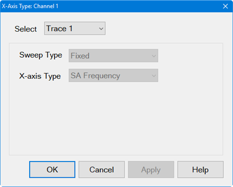
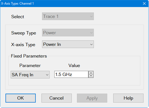
The X-axis Type dialog is used to set the displayed x-axis annotation for a selected trace in Modulation Distortion or Modulation Distortion Converter measurements.
Dialog for Modulation Distortion Measurement Class (MOD)
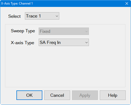
Dialog for Modulation Distortion Converters Measurement Class (MODX)
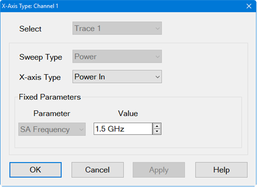
Select Trace N - Selects active trace. All Traces - Selects all available traces. Sweep Type - Based on the currently active sweep type for the selected channel. Fixed - Fixed sweep measures a modulated signal with a fixed carrier LO frequency and power level. The Sweep Type selection determines the available X-axis Type. This selection can only be changed from the Sweep dialog. Power - Power sweep sweeps the total power of the modulated signal. X-axis Type The X-axis Type setting defines the x-axis annotation for the displayed spectrum analyzer data. For Modulation Distortion Converter measurements, the x-axis annotation may be set to one of two frequency ranges: mixer input range and mixer output range. For example, if a mixer has an input frequency of 1 GHz and an output frequency of 10 GHz, the X-axis Type is set to SA Freq In, and PIn and POut are measured, PIn and POut will both indicate they are measured at 1 GHz, even though POut is actually at 10 GHz. If the X-axis Type is set to SA Freq Out, PIn and POut will both indicate they are measured at 10 GHz, even though PIn is actually at 1 GHz. For Modulation Distortion Channels (MOD) SA Frequency - SA display showing the SA frequency settings. Power In - Displays input power sweep. Power Out - Displays output power sweep. Measured CarrIn1 - Measured input band power. Measured CarrOut2 - Measured output band power.
For Modulation Distortion Converters Channels (MODX) SA Freq In - SA display showing mixer input range. SA Freq Out - SA display showing mixer output range. Power In - Displays input power sweep. Power Out - Displays output power sweep. Measured CarrIn1 - Measured input band power. Measured CarrOut2 - Measured output band power. Fixed Parameters (Power Sweep Type only) Value - Displays the spectrum analyzer frequency set in the Sweep dialog for a power sweep. Parameter - (Modulation Distortion Converters Channels only) Selects either SA Freq In to display mixer input range or SA Freq Out to display mixer output range.
|
|