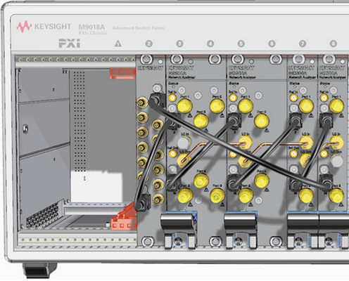
M98xxA, P50xxA/B and P93xxB can output/input the signals to communicate with external peripherals via control ports (master and sub) on the front panel. The Y1731A-001 I/O adapter allows you to access the signal via SMB connectors.
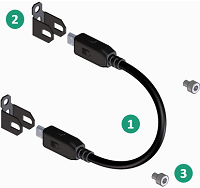
The cables should be connected like the following figures. The Y1731A-001 is a passive adaptor which does not require the power. Installing it into the PXIe chassis is not necessary. You can use it outside of the PXIe chassis.
The angle and screws prevent the cable from coming off.
 |
No. |
Part Number |
Description |
Qty. |
1 |
M9800-61601 |
Cable Assembly, Control 150mm-LG (This cable is not furnished with Y1731A-001) |
1 |
|
P5000-61603 |
Cable Assembly, Control 175mm-LG |
|||
M9800-61605 |
Cable Assembly, Control 500mm-LG |
|||
2 |
M9800-01201 |
Angle, Control Cable Assembly |
2 |
|
3 |
0515-4351 |
Screw-SKT-HD-Cap HEX-SKT M3X0.5 4mm-LG |
2 |
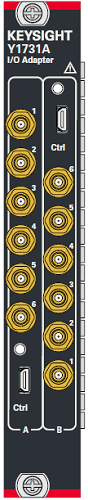
Sides A and B on the Y1731A-001 are identical. You can connect the Ctrl M or S with both sides.
Port Number |
Function (Factory Default) |
Alternative Function |
1 |
High level output |
|
2 |
High level output |
|
3 |
Arbitrary input |
|
4 |
Arbitrary input |
|
5 |
RF pulse modulation input |
None |
6 |
Arbitrary input |
None |
Port Number |
Function (Factory Default) |
Alternative Function |
1 |
Trigger input |
None |
2 |
Pulse synchronization input |
Aux Trigger In |
3 |
Arbitrary input |
|
4 |
Arbitrary input |
|
5 |
High level output |
|
6 |
High level output |
|
Signal name |
Input/Output |
Description |
/READY FOR TRIGGER |
Output |
Indicates that the instrument is ready for triggering. This signal is changed to the Low level when the instrument is ready for receiving a trigger signal. With the point trigger function on, it goes to the Low level when the instrument is ready to accept the trigger signal for the first point and goes to the High level when the trigger signal for the first point is received. When measurement of all measurement points is completed and the instrument is ready to receive the trigger signal for the first point of the next sweep, this signal goes to the Low level again. |
/EXTERNAL TRIGGER |
Input |
An external trigger signal. When the trigger source is set to the "External," this port generates a trigger in respond to the trailing edge of a negative pulse. |
/INDEX |
Output |
Indicates that analog measurement is complete. The /INDEX signal changes to the Low level when analog measurement (all sweeps of all channels) is complete. When the handler receives the signal, it assumes that it is ready to connect the next DUT. However, no measurement data are available until data calculation is completed. When the point trigger function is on, it goes to the High level before staring measurement of the first measurement point and returns to the Low level after completing measurement of all measurement points. |
/SWEEP END |
Output |
A sweep completion signal. When measurement (all sweeps of all channels) and data calculation are completed, this signal provides a negative pulse. |
PULSE SYNC IN |
Input |
Pulse generator synchronization trigger input |
RF PULSE MOD IN |
Input |
RF source pulse modulation drive input |
Pulse Output 1 (P1) |
Output |
Hardwired pulse train output #1 |
Pulse Output 2 (P2) |
Output |
Hardwired pulse train output #2 |
Pulse Output 3 (P3) |
Output |
Hardwired pulse train output #3 |
Pulse Output 4 (P4) |
Output |
Hardwired pulse train output #4 |
Source port (#S) external switch control output |
Output |
Indicates that the source signal is out. This signal is changed to the Low level when the source signal is out. |
Receiver port (#R) external switch control output |
Output |
Indicates that noise sweep. This signal is changed to the high level when the target port is used in a sweep for noise measurement. |
LO signal of module (#M) external switch control output |
Output |
Indicates that noise sweep for dual-band parallel mode (option). This signal is changed to the high level when the target port is used in in a sweep for dual-band parallel noise measurement. |
SMB Port No. |
1 |
2 |
3 |
4 |
5 |
6 |
Ctrl (Micro HDMI) Pin No. |
12 |
14 |
17 |
18 |
2 |
15 |
The function for each pin can be assigned by Interface Control and SCPI Command.
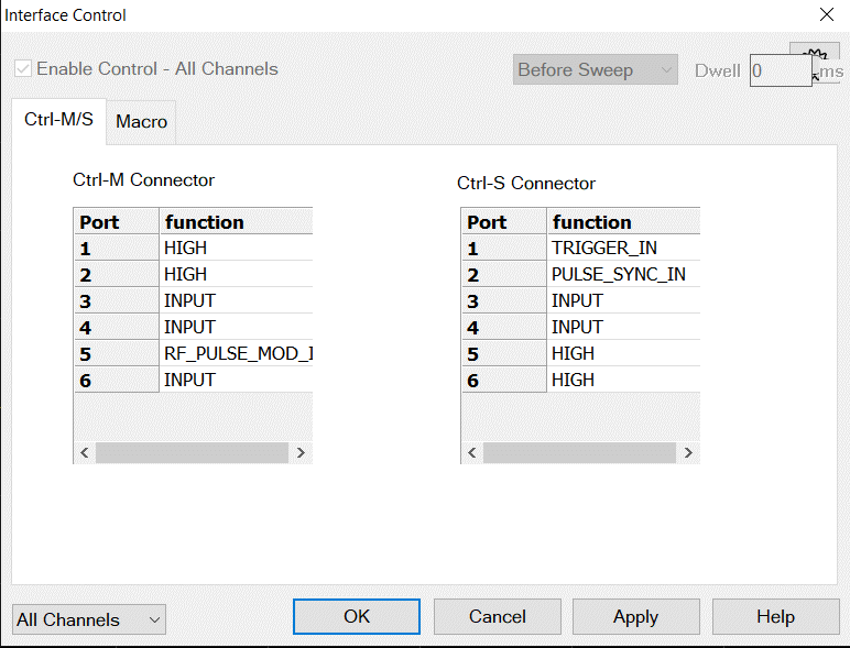
Function When a white cell is clicked, a drop down list appears to show functions assignable to the specified port.
OK / Apply Applies the settings and closes the dialog box.
Cancel Does not apply changes that were made, and closes the dialog box.
See CONTrol:SIGNal:KDMI SCPI commands to set or read the signals, assign the alternative functions for the test port. The assigned settings are preserved for each system configuration even after preset, firmware restart and power on/off.
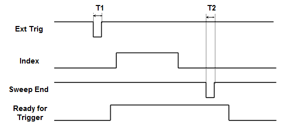
Trigger Timing |
|
All signals are active low. T1 = 1 ms External Trigger pulse width T2 > 10ms Sweep End pulse width (both High and Low) |
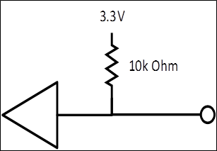
All I/O Input and Output lines are TTL compatible.
Lines carrying information IN (or bidirectional) to the VNA from the material handler.
Maximum Input Voltages: |
-0.5 V to 5.5 V |
TTL High level: |
2.0 V to 3.3 V |
TTL Low level: |
0 V to 0.5 V |
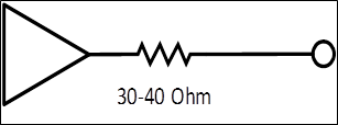
VNA Input and Input/Output Circuit Diagram
Lines carrying information OUT of the VNA to the material handler.
Maximum Output Current: |
-10 mA to 10 mA |
|
Output Current |
TTL High level: |
-5 mA |
TTL Low level: |
3 mA |
|
Output Voltage |
TTL High level: |
>= 2.0 V |
TTL Low level: |
0 V to 0.8 V |
|
VNA Output Circuit Diagram