Fixture simulator allows user to mathematically add (embed) or remove (de-embed) circuits to, or from, the measurements. Learn more on Fixture Simulator.
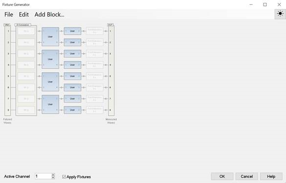
In the new fixture generator with the firmware A.14.40 and above, multiple fixturing elements can be combined in any order, creating infinite combinations. New SCPIs are created with the concept of fixture “blocks’ or “circuits”.
In the legacy fixturing, a few specific features are tied to specific ports.
Programming examples:
There are two important concepts:
Fixtures are built from right to left, the circuit elements are added from right to left. There is no way to insert a block to the right of already existing blocks. And unlike legacy commands, there is not one SCPI command to change the order of the features. Instead, the blocks must be created in the order desired.
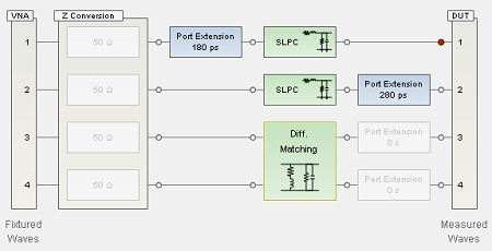
Example of a fixture:
When building a fixture, the circuit elements are added from right to left. So in this example, the S2P blocks are added first, and then the S4P blocks.
Note: These blocks always exist and user cannot create them. In order to move them to the appropriate place in the fixture, first create the fixture elements to the right, then send the “calc:fsim:draft:extension:port[n]:end” command to move the port extension to the left-most side of the circuit sections. If more fixture elements are desired to be added to the left of the port extensions, create them after the “calc:fsim:draft:extension:port[n]:end” command is sent.
Fixture elements are built on a “draft” fixture and then “applied”. The process should be:
First “discard” the draft fixture changes with CALC:FSIM:DRAFt:DISCard command. This copies the active fixture to the draft fixture.
Then build fixture using new Fsimulator Draft SCPI commands.
Lastly “apply” the draft fixture with CALC:FSIM:APPLy. This does a fixture computation (to ensure validity) and then the fixture is copied to the active fixture in the channel.
Fsimulator Draft SCPI commands, CALC:FSIM:DRAFt:XXX:YYY:ZZZ : These commands are used to query and set fixture values on a scratch fixture.
Fsimulator Active SCPI commands, CALC:FSIM:XXX:YYY:ZZZ : These commands are used to query ONLY fixture values on the active fixture.
The only exceptions to these commands are:
CALC:FSIM:APPLy which is same as legacy command
CALC:FSIM:POWer:PORT:COMPensate commands because they are not fixture building commands, but rather specify if the fixture is being used in the channel (and how).
CALC:FSIM:APPLy: Validate scratch fixture, copy to active fixture
CALC:FSIM:DRAFt:DISCard: Discard scratch fixture changes by copying active fixture to scratch fixture.
CALC:FSIM:RESet: Preset the fixture.
Notes
|
:CALC1:FSIM:DRAFT:DISCard
! Port Matching for port 1
:CALC1:FSIM:DRAFt:CIRCuit1:ADD SLPC,2
:CALC1:FSIM:DRAFt:CIRCuit1:VNA:PORTs 1
:CALC1:FSIM:DRAFt:CIRCuit1:EMBED:TYPE EMBED
:CALC1:FSIM:DRAFt:CIRCuit1:STATe ON
:CALC1:FSIM:DRAFt:CIRCuit1:PAR:L 3E-9
:CALC1:FSIM:DRAFt:CIRCuit1:PAR:R 0
:CALC1:FSIM:DRAFt:CIRCuit1:PAR:C 0
:CALC1:FSIM:DRAFt:CIRCuit1:PAR:G 0
! Port Matching for port 2
:CALC1:FSIM:DRAFt:CIRCuit2:ADD SLPC,2
:CALC1:FSIM:DRAFt:CIRCuit2:VNA:PORTs 2
:CALC1:FSIM:DRAFt:CIRCuit2:EMBED:TYPE EMBED
:CALC1:FSIM:DRAFt:CIRCuit2:STATe ON
:CALC1:FSIM:DRAFt:CIRCuit2:PAR:L 2E-9
:CALC1:FSIM:DRAFt:CIRCuit2:PAR:R 0
:CALC1:FSIM:DRAFt:CIRCuit2:PAR:C 0
:CALC1:FSIM:DRAFt:CIRCuit2:PAR:G 0
! Diff. Matching for ports 3 and 4
:CALC1:FSIM:DRAFt:CIRCuit3:ADD D4PMatching,4
:CALC1:FSIM:DRAFt:CIRCuit3:VNA:PORTs 3,4
:CALC1:FSIM:DRAFt:CIRCuit3:EMBED:TYPE EMBED
:CALC1:FSIM:DRAFt:CIRCuit3:STATe ON
:CALC1:FSIM:DRAFt:CIRCuit3:PAR:L 2E-9
:CALC1:FSIM:DRAFt:CIRCuit3:PAR:R 1E-4
:CALC1:FSIM:DRAFt:CIRCuit3:PAR:C 5E-9
:CALC1:FSIM:DRAFt:CIRCuit3:PAR:G 0
! Port Extension
:CALC1:FSIM:DRAFt:EXTension:PORT1:DELay 180E-12
:CALC1:FSIM:DRAFt:EXTension:PORT1:STATe ON
:CALC1:FSIM:DRAFt:EXTension:PORT1:END ' This command should be executed after adding all other blocks. Because adding a block resets the port extension block position.
:CALC1:FSIM:DRAFt:EXTension:PORT2:DELay 280E-12
:CALC1:FSIM:DRAFt:EXTension:PORT2:STATe ON
:CALC1:FSIM:DRAFt:SECTion:EXTension:ENABle ON
! Apply the circuit from draft to active.
:CALC1:FSIM:APPLY
:CALC1:FSIM:STATe ON