W-CDMA Concepts
Last Updated: January 15, 2009
W-CDMA Protocol Structure
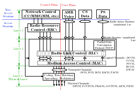
The W-CDMA protocol has a layered structure designed to give the system a great deal of flexibility. The two major parts are the Core Network (CN) and Radio Access Network (RAN). The structure of the RAN and the relationship of several key terms to it are illustrated in W-CDMA Protocol Structure . It is important to recognize that this figure is only an illustration. The exact structure, including the number and type of channels, number and type of user services, and the configuration of blocks in the structure will vary over time to meet the current needs of the system. The structures of the uplink and downlink are very similar; however, some types of channels exist in only one direction; while others exist in both.
The WCDMA structure is divided vertically into an "Access Stratum" and a "Non-Access Stratum", and horizontally into a "Control Plane" and a "User Plane". Protocol Layers 1 and 2 are in the Access Stratum. Protocol Layer three is divided between the Access and Non-Access strata. In layers 2 and 3 control plane and user plane information is carried on separate channels. Within layer 1 some channels carry only control plane information, while others carry both user and control plane data.
Radio Bearer Test Mode, TC, and Reference Measurement Channels
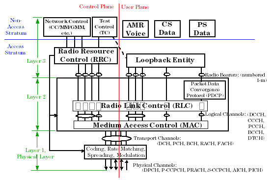
Radio Bearer Test Mode is a special mode of operation defined by the W-CDMA specifications. Its purpose is to provide for efficient manufacturing testing of a W-CDMA UE by offering a simplified mode of operation wherein the Test Set has complete control of the necessary UE functions. A Radio Bearer Test Mode connection to the UE is done via a special Test Control (TC) protocol entity and any User Plane radio bearers are terminated in a layer 3 loopback entity, rather than being connected through to a real service. In radio Bearer Test Mode the protocol structure appears as shown in W-CDMA Protocol Structure in Radio Bearer Test Mode
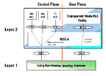
While it is still possible to configure layers 1 and 2 in any valid configuration in Radio Bearer Test Mode, the typical use of this mode is to set up the special test configurations known as "Reference Measurement Channels". The reference measurement channels are a defined set of configurations of layers 1 and 2 that provide stable, predictable behavior for radio testing. All aspects of these layers are explicitly defined by the definition of the Reference Measurement Channels given in the W-CDMA system specifications. The protocol structure of the Reference Measurement Channels is shown in W-CDMA Reference Measurement Channel Protocol Structure
W-CDMA Channels
"Channel" has several meanings in the W-CDMA system.
| Channel Name | Exists in Uplink | ||
|---|---|---|---|
| CPICH | Physical Channel | * | |
| S-CCPCH | |||
| * | * | ||
| * | |||
| * | |||
| * | |||
| * | |||
| * | |||
| * | * | ||
| Logical Channel | |||
| BCCH | Logical Channel |
Downlink Overhead Channels
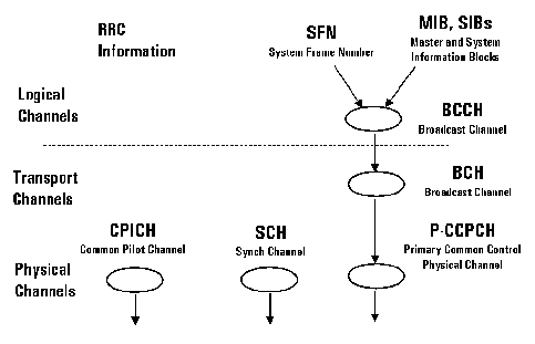
The overhead channels are transmitted continuously in each cell. They are used by the UE to synchronize to the cell, to identify the cell and the network, and to obtain information about how to access the cell.
- Common Pilot Channel (CPICH) - used to transmit timing and frequency reference information to UEs (mobile stations) which are used by the UE (mobile station) to find the primary scrambling code and to help determine its transmit power during open loop power control.
- Synchronization channel (SCH): includes the primary and secondary synchronization channels (PSC and SSC) that contain timing information to allow the UE to synchronize to the test set (or base station). It is time multiplexed with P-CCPCH.
- Primary Common Control Physical Channel (P-CCPCH) - used to transmit Broadcast transport channel (BCH) which provides system information to the UE. It is time multiplexed with Synchronization Channel (SCH) which is used to aid the UE synchronization to the network. In FDD Test operating mode, this channel consists of pseudo-random bit sequence (PRBS) data and a valid system frame number (SFN).
Channels Used for Call Setup
After the UE has identified a cell that it wants to access and has read the access information from the Broadcast Channel, it must register. Registration informs the network of the presence of the UE and is performed using the Location Update Procedure.
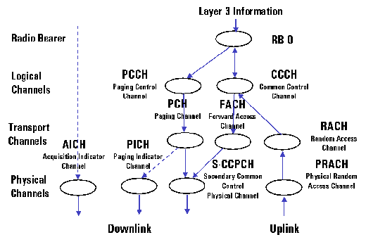
In order for there to be any communication between the mobile and the network a control connection must be established between the RRC entities in the network and the UE. This step is the same whether the purpose is registration, mobile initiated call setup, or network originated call setup. These channels are shown in W-CDMA Connection Setup Channels
- Acquisition Indication Channel (AICH) - used to acknowledge UE access request.
- Paging Indication Channel (PICH) - used to alert the UE of a forthcoming page message. In FDD test mode, the test set only provides a user specified bit pattern to allow the operator to verify that the UE is correctly decoding this channel.
- Secondary Common Control Physical Channel (S-CCPCH) - used to transmit pages and signalling to idling UEs.
- Physical Random Access Channel - used by the UE to make its initial transmissions to the network.
