Overview of the Power Device Model Generator (PEMG)
Before Running the PEMG Software
Before running the PEMG software, you must have Keysight’s Advanced Design System (ADS) Simulation software installed on your system. For detailed information, click here: www.keysight.com/find/eda then click Advanced Design System (ADS).
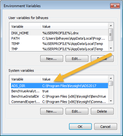
- To open the Environment Variables window, type “Environment Variables” in the Windows Search Field. In the Advanced tab, select the Environment Variables button.
- Click the New... button.
- Enter “ADS_DIR” as the Variable name.
- Enter the path name where the Keysight ADS was installed as the Variable value.
- Click OK twice to exit the Environment Variables setup dialog.
Running the Power Electronic Model Generator (PEMG) Software
-
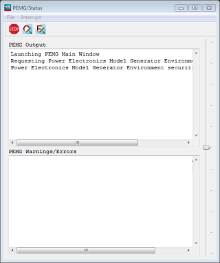
After installing and licensing the PEMG software, launch the software from the Windows Start button > IC-CAP 2018 > Power Electronics Model Generator. This opens the PEMG Main Window and a Status Window:
-
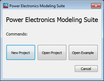
Click New Project to start a new project and import characterization data from the PD1000A software.
-
Open Project allows you to open an existing project.
-
Open Example allows you to open example projects to understand the software.
-
-
Click New Project and select the device type you want to model - either GaN ASM-HEMT, Keysight IGBT, or Keysight Si/SIC Power FET.
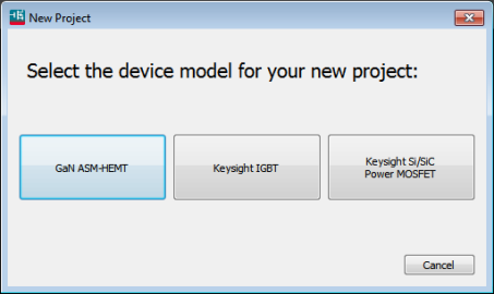
- For GaN devices, a model used by the Compact Model Coalition (CMC) is used.
- For IGBT and Si and SiC Power FET devices, models developed by Keysight are used.
Make sure you select the data model appropriate for your device.
Project Page
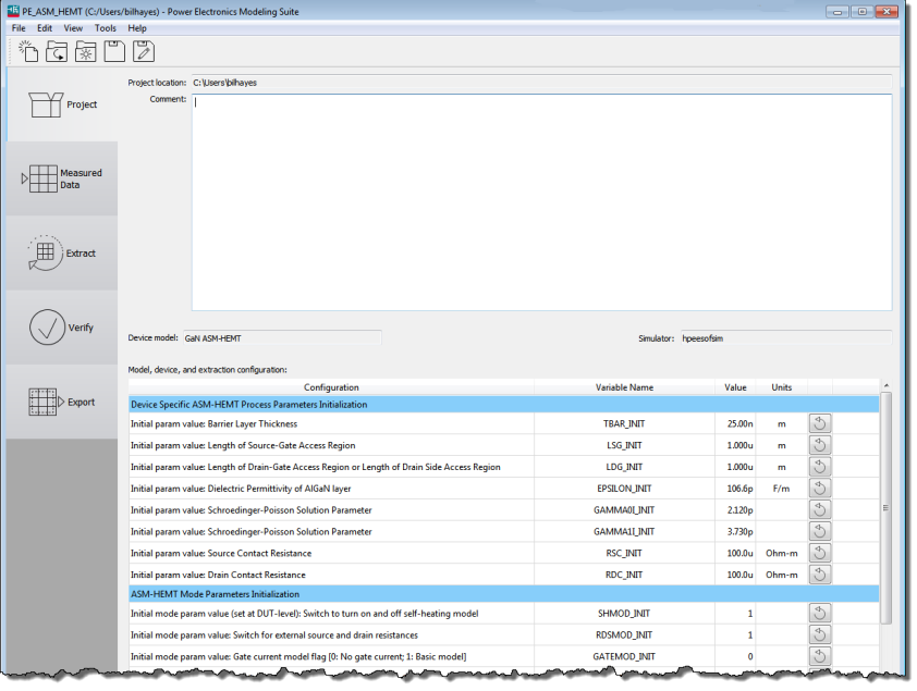
- Selecting a device opens the new Project screen. Notice the five tabs on the left side of the display.
The Project screen allows you to record specific information about the specific project. In the screen capture above, we chosen a GaN ASM-HEMT device.
- Project Location: shows the working directory of the PEMG project.
- Comment: This field allows you to add information relevant to the project such as notes on the device, what the project is for, etc.
- Device Model: Shows the currently loaded device model for the project.
- Simulator: Shows the simulator used for the extraction and model.
- Model initialization Table: The Model Device and Extraction Configuration table lists the minimum or user specific model related information. The parameter values are required to allow model extraction.
Measured Data Page
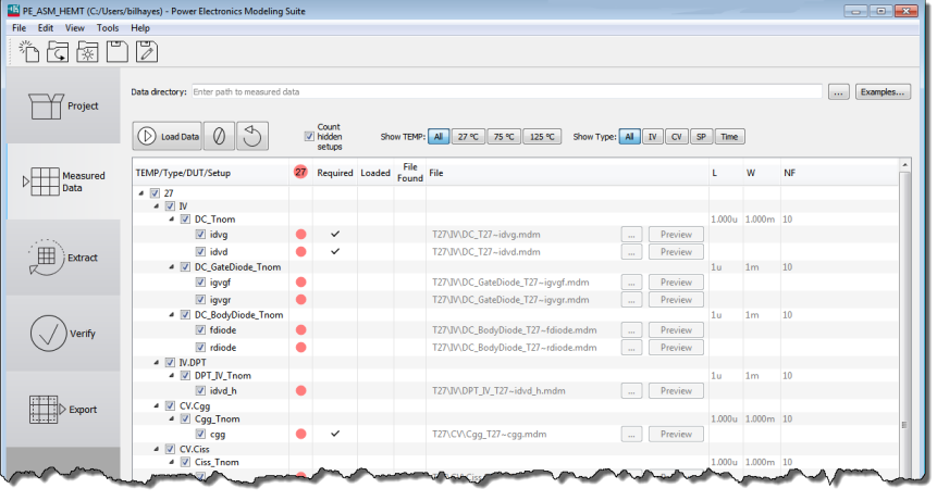
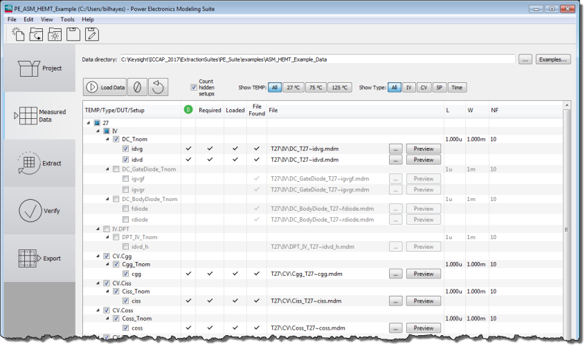
- After entering any information about the project in the Comments field, select the Measured Data tab on the left side of the screen. This opens the Measured Data screen:
Pay close attention to the various columns. Next to the column with the red circles is the Required data column; check marks indicate the minimum data required for the PEMG software to model the device.
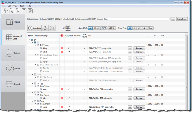
At the top of the screen is a Data Directory: field. Click the button with three dots and navigate to the directory where the PD1000A measurement results are stored in *.mdm files. (See Output File Structure for more information about the output directory and .mdm files.)
Check marks appear in the File Found column indicating that required data files were found in the specified directory.
Click the
button. This loads the device characterization data from the specified Data Directory files.
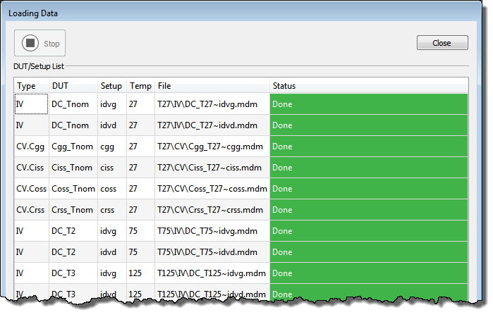
Click the Close button at the top of the Loading Data screen.
The next screen indicates the data files that were loaded into the PEMG software.
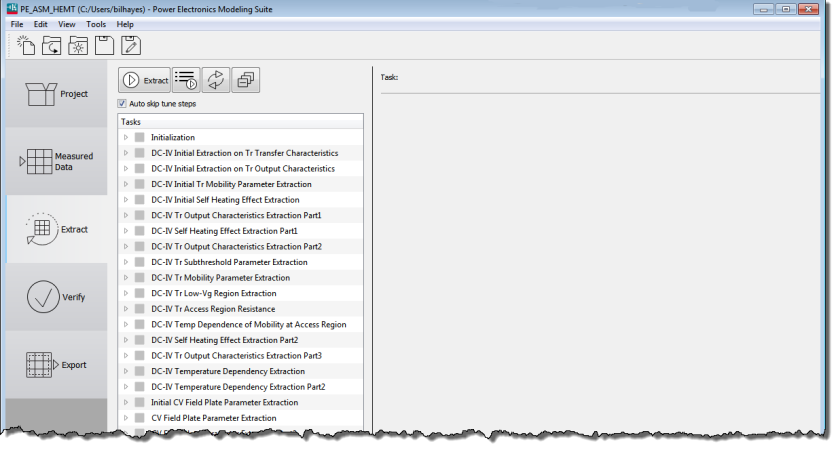
Extract Page
- Select the Extract tab on the left of the display. Click the
 button
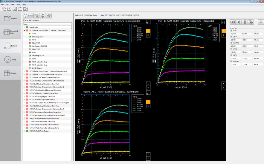
- Close the Extracting Parameters screen.
Expand items in the Tasks list to show the status of the various tasks. Mouse over the icons to show the status.
Verify Page
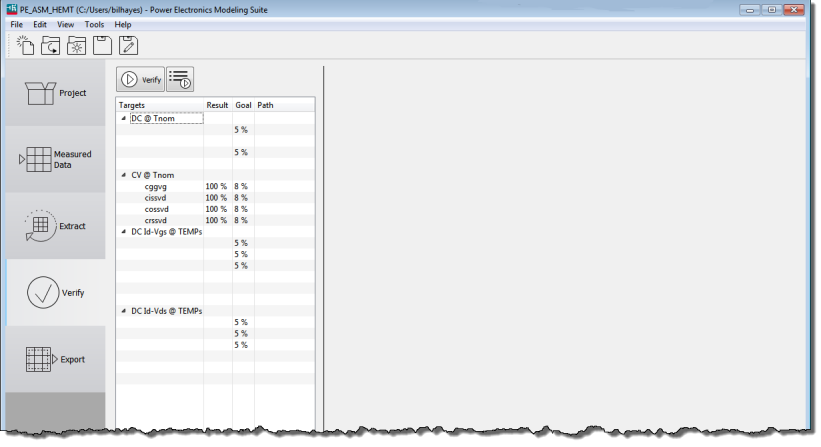
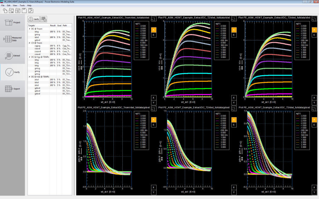
- Select the Verify tab at the left of the screen.
- Click the
 button. After verifying the parameters, close the Verify Parameters screen.
Export Page
-
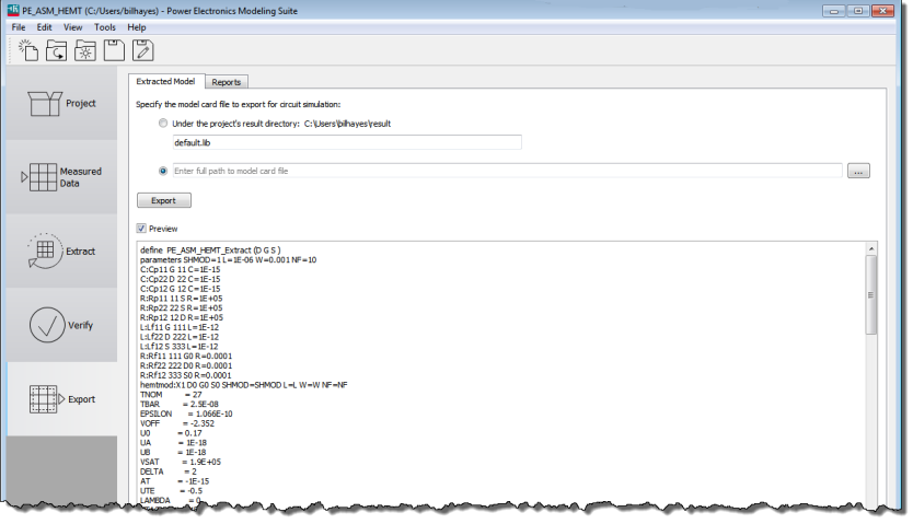
Select the Export tab on the left of the display.
-
In the Export screen, you can specify the file name in the project directory for the model card file. You can also create reports of the of the extracted model.
- Click the
 button the export the device characterization model to the specified directory. The data is now ready for circuit simulation.
