IEC60747-8
This chapter first describes the important parts of the IEC 60747-8 standard with regards to switching times and energies. Afterwards it gives some notes and explains how PD1000A software adapts this standard or deviates from it. The standard is applicable for discrete (according to title) FETs. These include J-FETs and both insulated-gate depletion/enhancement FETs. Applicable to n-channel types. Circuits can be adapted for p-channel types by changing polarities of meters and power supplies.
Test Setup
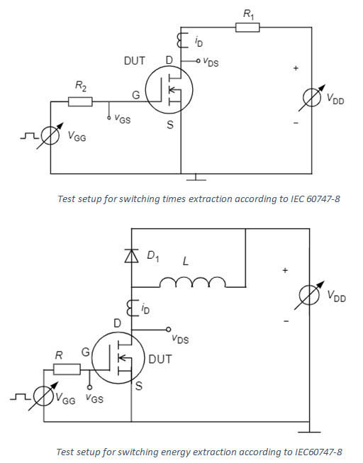
There are different measurement setups for switching times and switching energies defined in the standard.
Algorithm

We use a clamped inductive load test setup for both times and energies.
Voltage and Current Levels:
- Some levels are not defined properly in the standard
- 0.9 VGS and 0.1 VGS is with reference to 0 V, not the negative gate voltage. Example: gate voltages of 20 V/-5 V would lead to 10 %=2 V and 0 %=18 V
- 0.1 ID is with reference to 0 A.
- 0.1 VDS and 0.9 V_DS: We measure VDS between pulses and use this as 100 % reference. 0 % reference is measured at the end of the first pulse while device is still fully turned on. This way 10 % is mostly able to be reached. Without this it is often not possible for high currents due to beginning of saturation etc.
- The levels are measured on the original signals, except for 100 % of IDS. To extract 100 %, the IDS signal is low pass filtered with a frequency of 10 MHz.
Start and End Times
- Currently software always searches first crossing of voltage/current levels searching from left to right. This can lead to smaller times or energies when there is a lot of ringing in the system etc.. Infineon suggested searching from the right for e. g. the end of integral for switching energy.
- Currently in PD1000A software, timing of turn-on 0.9 VDS is not the real time this value is reached but we use linear approximation of falling edge because of influence of parasitic inductance. Currently we look at 25 % and 75 % times and do linear approximation. This may not make sense if voltage drop by inductance is more than 25 %. The standard doesn’t mention anything, and it is difficult to implement reliably.
- The following formulars are used as start and end times of turn on/off:
- start time = turn on/off time
- end time = start + delay + rise/fall time

